I have a pair of Stancor Isolation Transformers connected in series as below:
Isolation #1 Isolation #2
------) (------ ------) (------
) ( ) (
) ( ) (
------) (------ ------) (------
230 120 120 230
1. If I connect the ground only between #1 and #2 would I risk electrocution?
2. If I tie the ground across TAPs, would I negate the benefits of isolation?
3. If I connect it in parallel, would this be equivalent to balanced transformer as discussed elsewhere in the forum?
4. Currently the transformer is causing trips quite frequently, how can I reduce this problem?
Thank you all for your informed advise.

I would ground one of the 120V leads between the transformers. Effectively acts as a shield between first primary and last secondary.
I am not familiar with code requirements in Singapore, but they will govern what you are supposed to do with the 230V secondary with regards to grounding. I would strongly support either grounding one lead (now becomes the neutral) or grounding the center tap (which you do not show as being available).
Floating systems in general are not friendly, and should be avoided unless you plan on performing open heart surgery..
There is no need to ground any of the outputs from the isolation transformer but the amplifier case and any exposed metal must be connected to the power outlet earth and ultimately to the building earth, I am assuming that the code in Singapore is similar to Australia most commonwealth countries derived their electrical code from the UK
AFAIR only extra low voltage equipment is exempt from the case earth requirement. I doubt that an isolation transformer would make the equipment fall under the double insulated earth exemption.
AFAIR only extra low voltage equipment is exempt from the case earth requirement. I doubt that an isolation transformer would make the equipment fall under the double insulated earth exemption.
I second zigzagflux and would ground one of the 120V lines.
I have an isolation transformer in my audio system and it works better if the secondary is referred to ground ... much more quiet at startup.
In floating mode you'll notice that the voltages between the two lines, with reference to ground, are quite different. In my case I had 40VAC and 80VAC, respectively. I am not sure if that is of any significance to the connected end devices down the line, but at least it's not pleasing to the eye.
a 230:120Vac feeding a 120:230Vac will not give 230Vac.
You need to look at turns ratio for the two transformers.
You can measure turns ratio fairly closely by measuring the open circuit secondary voltage.
Then take account of the voltage drops through the four windings.
If either of the transformers has a dual primary then use the dual primary as the isolated output. The centre tap of the dual primary goes to PE. This gives you an isolated ~110Vac from each of the two output windings. ~220Vac from the out of phase windings.
Last edited:
Thank you all for your advise, the transformer actually has 3 wires, I managed to obtain the the actual schematic from Stancor:
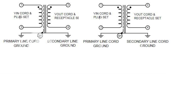
I traced the lead in and lead out ground are completely isolated. If I short the ground between the transformer pair it would still be floating. I am concern on the proper connection and safety aspect of the connection.
Since I have two pairs, what are the modes of connection for the ground? Should I short all the 4 grounds then?
I noticed there is a SH sign on the schematic, does it signify the shield is connected to the primary ground? Should I connect the secondary to earth separately
There seem to be two school of thought here
1. to ground at the transformer
2. common ground at amp
What are the pro and cons of each? Thanks
Assuming you will be connecting 3-1 and 4-2 in the middle of the drawing, and your statement that you are concerned about safety, then I recommend:
Tying all grounds together. It looks like the shield is already bonded to ground, but if not it should be.
Grounding 4-2 in the middle of your drawing.
Bonding 4 (far right of the drawing) to ground. Don't be surprised to hear many suggestions to leave the final secondary isolated. Besides the fact that code does not permit this (at least in the US), there is no demonstrable benefit to leaving the winding floating. On the contrary, there are documented IEEE standards that detail the problems with ungrounded systems.
You will have no ground loops with this method, and will have fantastic common mode filtering of RF and noise in your power supply. If you wanted to reduce differential noise, you could add a X capacitor across the middle 120VAC lines.
I don´t see why would anyone ground the secondary when this is supposed to be isolation transformer.
Because the transformer performs galvanic isolation, with all its benefits, regardless if the secondary is grounded or not. It is a separately derived system regardless if the secondary is grounded or not. By bonding, all you are doing is providing a stable reference for the secondary.
Floating and isolation are not synonymous by any stretch in power systems. In general, isolation is good, floating is not.
Maybe it would be appropriate to get some clarification from pirastro on his need for using an isolation transformer. As noted in post #5, a floating output is really only needed in medical applications, and there they have additional line isolation monitors to watch over the system (so in reality they are balanced high impedance grounded systems, not actually floating).
Sure, a floating system allows one to touch any one of the two leads without receiving a shock. Question is why would you desire this? Do you plan on building a compromised amp that risks exposure of energized conductors? Experience shows grounded systems are safer in all but the most specific supervised applications. Even balanced power systems are solidly grounded, and those are intended for professional audio equipment.
The purpose of an isolation transformer is to develop a fresh ground, one that is noise free. Since current must travel in a loop, with only one ground at the secondary, you break ground current from flowing in the secondary system. Ground noise/loops in the primary are unable to contaminate the secondary.
")
zigzagflux, thank you so much for clarifying the connection
AndrewT, I intend to connect this to a power strip to power my audio gears
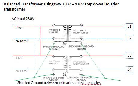
I like the idea of balanced trans, Kubeek you suggested I connect the 120V in series, how should I join the secondaries labelled b1 - b4?
Alternate to shorting the ground, is there any benefit of metalsculptor suggestion of separate grounding point for a single equipment to avoid ground loops?
Thank you all,
AndrewT, I intend to connect this to a power strip to power my audio gears
I like the idea of balanced trans, Kubeek you suggested I connect the 120V in series, how should I join the secondaries labelled b1 - b4?
Alternate to shorting the ground, is there any benefit of metalsculptor suggestion of separate grounding point for a single equipment to avoid ground loops?
Thank you all,
- Status
- This old topic is closed. If you want to reopen this topic, contact a moderator using the "Report Post" button.
- Home
- Amplifiers
- Power Supplies
- Isolation transformer connection