I would like to trigger the power-on of a SMPS based amplifier (Hypex SMPS+UCd) using the audio signal. I have seen that it is possible to swith on the SMPS module by applying a 3-12 V DC. Searching the forum I found only references to external 12 signals which could be used to power on the SMPS module.
But is there a simple way, or commercial module, which takes the audio signal (coming from a preamp with possibly low voltage at low listening volume) and when detecting a signal, provides the necessary max 12 V and, after some time without input, allows to switch off the SMPS?
(PS: I enjoyed this features on some commercial amps I used for central/surround channels in an AV system, only turning them on when using actual surround)
Thanks in advance
Thanks,
Found Signal Detecting Auto Power-On Unit but it goes beyond my present skills in electronics.
I have in the meanwhile found Xantech Audio Sensor Module - SMAUD01 - Smarthome which can be used together with
Xantech Current Sensor Connecting Block - CSM1 - Smarthome, but I suspect it is rather expensive with regard to the simple thing I expect it to do ?
I don't know of any commercial ones.
Easy to DIY one.
A low power FET opamp configured as mixer with 10meg or more input impedance to "detect" L/R. Use high gain so the signal clips to the rails and feed to a retriggerable delay so that power stays on for a predetermined time in absense of audio.
Can be elaborated on to provide opto isolation to trigger a PSU etc.
I guess I could also use Audio Signal Controlled Relay Switch Module (CPM011) adding a control on the maximum input voltage (rectifier+zender ?) with the relay switching on/off the 12 V controlling the amp.
As the module itself needs 12 V all I would need to add is a sufficient stable 12V DC source.
Does this sound ok for you ? Or did I miss something (i'm a real novice )
)
As the module itself needs 12 V all I would need to add is a sufficient stable 12V DC source.
Does this sound ok for you ? Or did I miss something (i'm a real novice
)The pdf on that link leaves a lot of question marks (literally ) For example, input impedance 1k ????
If they don't know who does...
Yes in theory it's OK but if it does have 1k input impedance then that is too low really. You don't want that across a line level audio feed. Also how long does the output stay active when audio removed ? You don't want the SMPS going off between tracks or changing a CD. You need a delay... perhaps as long as 5 minutes... but only you can answer that.
) For example, input impedance 1k ????If they don't know who does...
Yes in theory it's OK but if it does have 1k input impedance then that is too low really. You don't want that across a line level audio feed. Also how long does the output stay active when audio removed ? You don't want the SMPS going off between tracks or changing a CD. You need a delay... perhaps as long as 5 minutes... but only you can answer that.
The hypex can be put into standby by applying a voltage between 3 and 12 V
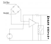
Does the following circuit ouline makes any sense (sorry, I’m a total novice).
The source voltage could be 12 V dc if there is an opamp which can work with it.
A few questions (if the first step, does it make sense, is passed) :
-are there opamps which present a sufficiently high impedance to the line in ?
-which kind of delayed relay should I look for (my badly drawn box on the right part)
-how can I be sure the line noise will not trigger the thing ?
-what kind of resistence I should put (needed because otherwise shortcut when signal)
Attachments
You're close, but the refinements needed to make it work take you the Rod Elliot circuit you linked to. Issues are undefined off state of comparator, comparator can't deliver the current needed to drive a relay.
Question - you apply voltage to get the hypex into standby or remove a voltage?
A caveat with the ESP circuit - either drive it from a single channel or convert the input buffer to an inverting configuration. As drawn there is a lot of crosstalk between the channels.
Question - you apply voltage to get the hypex into standby or remove a voltage?
A caveat with the ESP circuit - either drive it from a single channel or convert the input buffer to an inverting configuration. As drawn there is a lot of crosstalk between the channels.
Last edited:
You're close, but the refinements needed to make it work take you the Rod Elliot circuit you linked to. Issues are undefined off state of comparator, comparator can't deliver the current needed to drive a relay.
Question - you apply voltage to get the hypex into standby or remove a voltage?
A caveat with the ESP circuit - either drive it from a single channel or convert the input buffer to an inverting configuration. As drawn there is a lot of crosstalk between the channels.
The voltage applied to the hypex gets it into standby. Simply not connecting the cable means he will be on when the main power is on.
In my case I plan a mono installation, so single channel in any case.
The problem of the comparator not able to deliver the current to the relay, is this always the case or can it avoided by selecting matching opamps and relays ?
If the latter is possible and with the mono system, could the ESP circuit be simplified to an extend where I can try, or conversely can my own naive tentative be corrected without too much complications?
Thanks already for all the feedbacks.
Do you know how much current the module needs to be driven into standby? You might be able to drive the standby pin directly from a comparator, if you make it go high when no audio is present. You'd want to add a bit of delay to hold it on and prevent amp cycling during quiet moments. Although if the ESP circuit scares you we probably shouldn't be talking about morphing it into something else.
The issue with the comparator driving a relay directly in this circuit is twofold. One, a typical NE5532 can deliver ~35 mA but the output current could be as low as 10 mA. That may not be enough to reliably switch your relay. Secondly, without D1, C4, R11 in the ESP circuit the relay would cycle when the signal drops below a certain threshold.
The ESP circuit works fine with only one input connected. I built it, then clipped one input when I discovered the crosstalk. Works as intended.
I can't see it being simplified and working the way you want. U1A and surrounding parts amplify the signal so that it is high enough to operate U1B's comparator even at low levels. The comparator is the switch. When it goes high, it charges C4 and turns on the mosfet to trigger the relay. C4 and R11 form a hold on delay so that the relay stays tripped when the signal falls below the threshold for a moment. Without it the relay would operate with every cycle of the signal. D1 prevents C4 from discharging through U1B when its output is low.
Basically you need to build a simple Op-Amp amplifier with VERY HIGH gain. This will input the Audio Signal and amplify the 100mV or so up to 9V PLUS. Then all you need to do is rectify the output and feed it into an INTEGRATOR (Basically an RC Circuit) and use the DC output to power ON a relay.
You need nothing special as the quality of the audio into the relay IS NOT an issue. A simple 741 will do the job.
You need nothing special as the quality of the audio into the relay IS NOT an issue. A simple 741 will do the job.
Note that the OP has stated a limited knowledge of electronics. We're not going to help him much with verbal circuit descriptions. If there is a dual voltage supply available for the opamp, Andy's concept would work fine. If you only have a single rail, the ESP circuit is about as simple as you can find ready to go. D1 is the rectifier, C4 and R11 form the integrator Andy mentioned.
Realistically, you don't need a relay, just replace the relay with a 10K resistor and use a ZVN3310 for Q1.Connect the Hypex PSU standby pin to the junction of the resistor and Q1. When C4 is charged Q1 turns on and pulls the output voltage to almost 0.
I only mentioned the NE5532 because they are inexpensive, in my parts bin and I had a data sheet handy. Yes, any old opamp will do.
Even with a gain of 100 as shown in Rod's circuit, I find that the system takes a while to trip on at low signal levels. The capacitor takes a finite amount of energy to charge, and even with the comparator going to 12V there is a turn on delay.
Don't forget that you'll need a 12V supply - a 9VAC transformer (wall warts work, too), a bridge made with 1n4007s and a 100 uf 16 v cap will suffice. Be sure to provide a fuse in that transformer's primary. If you still want a relay it can be something cheap, you don't need a huge mains rated relay. A 12v DIP relay would work fine. (DS2Y type or cheaper)
Last edited:
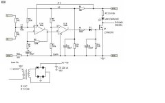
Here's Rod's circuit modified as I suggested for relay free operation. The optional LED can be any color. It will be on when the circuit pulls the signal to ground. The value of R12 determines the brightness of the LED It can go down to 1K with 1/4W resistors to get 10 mA in a red LED. If you don't want an LED, just connect the resistor to Q1. Hypex doesn't specify the current to be supplied to the standby pin, but I assume it is less than 1 mA.
The LED current will be approximately (12-Vled)/R12. Power in R12 is the current multiplied by 12-Vled. If you get a dissipation over .125W, use a 1/2W resistor for R12. Vled is roughly 1.2V for red, 2V for green and 5V for blue.
I also added a psu - all diodes are 1n4007 or you can use a ready made 1A bridge.
Attachments
Thanks to all of you, I'm getting slowly the picture, eg the C4-R11 part is simply the delay via a discharging RC circuit; in my naive implementation I had assumed off-the-shelf delayed relays exist, incorporating part of the circuit.
I could probably be able to implement the circuit (not very 'nicely', but I have enough place and it is not in the audio path), my biggest problem will probably chasing the components (not knowing which one can be replaced by similar ones). As a novice I obviously do not have a lot of them in stock ...
In all cases, I will make provision of a switch which allows to disable the whole autosensing and provide zero volt the the hypex ...
I wonder why hypex does not provide such an autosensing option on their SMPS ? (hopefully they are reading us ;-) )
If you use the LED you can see that the circuit operates as intended before hooking up to your PSU (suggestion use a red LED and 1-2K for R12). All resistors can be 1/4 watt, cheapest industrial grade. Any dual opamp will do. NE5532, TL072, 1448, whatever is cheapest. The diodes can be 1n400x including D1. I buy 1n4007 in large quantities and use them all over the place, but any of the series will do. The electrolytic caps can be anything rated for at least 16V. If you want your amp to stay on longer after the circuit detects silence, add more 100 uf caps in parallel with C4. Each one will approximately double the time it takes to turn off. The smallest 9VAC transformer is god enough. Bigger won't hurt, except in your wallet. None of the parts are critical, and Rod chose standard values so they should be easy to find. Try Farnell.
This is a down and dirty utility circuit. A good chance to hone your skills building a circuit that is tolerant of less than perfect implementation. We're here if you run into trouble.
This is a down and dirty utility circuit. A good chance to hone your skills building a circuit that is tolerant of less than perfect implementation. We're here if you run into trouble.
I used a very similar idea to Rod Elliots many years ago in a headphone amp,
http://www.diyaudio.com/forums/soli...aired-setup-new-television-2.html#post2419559
The Opamp I used was a TLO62 for both low power and to allow R1/2/3 etc to be in the 10meg ohm region. That eliminates any question of whether the loading of the circuit is detrimental to the audio. The low power meant it could be powered from a nicad, with the main supply taking over when audio detected. As for detecting audio, a frequency response of around 100 to 1khz is fine so roll off etc isn't a problem.
I added a CMOS 555 timer between the opamp output and the FET (VN10KM) driving not a relay but an opto triac giving a defined delay of 5 mins. The FET was still needed as the 555 could drop out in normal silences, the FET providing a "carryover".
As Bob say, this kind of circuit has endless possibilities. It's nice if possible to design for ultra low power and to try and incorporate any scheme into using the existing PSU's available.
Is anyone still active on this thread? BobEllis maybe?
I built this trigger, but can't get it to work properly. When I connect it to the audio output of the DAC, it works. After a couple of minutes the LED switches off when there is no audio signal present.
Problem is that when I connect the output to the SMPS, the LED switches on and won't turn of again. Is this a grounding problem and is it possible to solve this without adding a relais or optocoupler?
Any help would be appreciated.
- Status
- This old topic is closed. If you want to reopen this topic, contact a moderator using the "Report Post" button.
- Home
- Amplifiers
- Power Supplies
- Enable 12V trigger with audio signal