Hi All,
I want to design 8kw Welding SMPS (24V@300A), of course i know it's very hard to do that with one SMPS, so i'm thinking of paralleling 4 Full bridge SMPS, although .. i want to use only one Gate driver, and mains rectification circuit, so I'll only use 4 transformers and 16 Mosfets witch i found that "IRFP460" is best suited for 230VAC Input, of course I'll need any help and any designs available, but let me start with some newbie questions :
1- can i use full bridge topology as is? with no cab or external diodes, also why using tank cap in series with main transformer, In H-Bridge doing that destroyed my 2 IRFP460, without it and without snubbers too all works fine!
2- what's the best frequency th work on? i,ve noticed that lower freq produce more output power but below 20Khz mosfets says good bye!
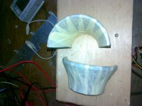
3- about transformer, before i was able to runaway with PC PS transformer re-winded to "60/30" with no gap, but i want to know what's the primary turns stands for? i mean shall it be more comfortable for the fet's if i re-wind the transformer with "120/60"?, also about gap, i know that i stores energy but let's face the truth is the any need for it? practically?, any way i'm welling to use the semi-toroidal ferrite which i found on CRT, Carzy hah?, it's the only big enough one that sufficient to current i want
4- why need for coil after secondary rectification, isn't one big cap enough?
5- my Gate Drive voltage is about 13V > 10V on full load, is that okay or i shall increase or decrease it?
6-What's is PFC, and am i going to need it?
7- as i want to use it in welding, am i going to need secondary rectification at all?
please no one tell me about reading i'm reading and practicing about 6 months now about SMPS but i can't find explanation to everything you know!
All Work With TL494, And 594 !
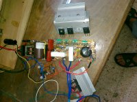
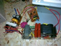
And I've attached some Photos if any one would like o watch
I want to design 8kw Welding SMPS (24V@300A), of course i know it's very hard to do that with one SMPS, so i'm thinking of paralleling 4 Full bridge SMPS, although .. i want to use only one Gate driver, and mains rectification circuit, so I'll only use 4 transformers and 16 Mosfets witch i found that "IRFP460" is best suited for 230VAC Input, of course I'll need any help and any designs available, but let me start with some newbie questions :
1- can i use full bridge topology as is? with no cab or external diodes, also why using tank cap in series with main transformer, In H-Bridge doing that destroyed my 2 IRFP460, without it and without snubbers too all works fine!
2- what's the best frequency th work on? i,ve noticed that lower freq produce more output power but below 20Khz mosfets says good bye!
3- about transformer, before i was able to runaway with PC PS transformer re-winded to "60/30" with no gap, but i want to know what's the primary turns stands for? i mean shall it be more comfortable for the fet's if i re-wind the transformer with "120/60"?, also about gap, i know that i stores energy but let's face the truth is the any need for it? practically?, any way i'm welling to use the semi-toroidal ferrite which i found on CRT, Carzy hah?, it's the only big enough one that sufficient to current i want
4- why need for coil after secondary rectification, isn't one big cap enough?
5- my Gate Drive voltage is about 13V > 10V on full load, is that okay or i shall increase or decrease it?
6-What's is PFC, and am i going to need it?
7- as i want to use it in welding, am i going to need secondary rectification at all?
please no one tell me about reading i'm reading and practicing about 6 months now about SMPS but i can't find explanation to everything you know!
All Work With TL494, And 594 !
And I've attached some Photos if any one would like o watch
Attachments
What type of welder is it GMAW, SMAW Tig? 24V is only enough for a 220A GMAW machine for these machines the filter capacitor if used is before the output choke. TIG and SMAW like open circuit voltages from 60 to 80V and no capacitors.
As for frequency that depends on the transformer, I would be looking for 400Hz or 1000Hz aircraft transformers or old mainframe PSU transformers then use the power side of an old VFD which will have all the IGBT's filter capacitors etc.
As for a PFC that depends on your supply, a poor man's PFC would be a line reactor before the bridge rectifier.
A welder is not a simple power supply it has a specified output impedance.
Last edited:
Sorry, i don't know the types, but if you please tell me about the difference, after all I'll be welding using argon and electricity, after some googling i think it's SMAW/GTAW/TIG also What voltage you suggest to work on?
actually i use the filter capacitor before the output choke, that grants me more output power with no destruction to the fets
why too low freq? that will result in bigger transformer, is it better for mosfets to get under 30Khz?
what you mean by line reactor?
actually i use the filter capacitor before the output choke, that grants me more output power with no destruction to the fets
why too low freq? that will result in bigger transformer, is it better for mosfets to get under 30Khz?
what you mean by line reactor?
That sounds like TIG in which case having both AC and DC available is more useful. An open circuit voltage of at least 60V an no more than 80V (for safety reasons) is advisable. The power supply should have high impedance and approach constant current behaviour rather than constant voltage An arc is a discharge type load, similar to discharge lighting and these types of load are most stable when fed from a voltage higher than the discharge (arc) voltage through an inductance. Familiarise yourself with conventional welders to get an idea what is needed for an SMPS. There is a standard arc voltage drop formula used by the AWS for designing welder PSU'sSorry, i don't know the types, but if you please tell me about the difference, after all I'll be welding using argon and electricity, after some googling i think it's SMAW/GTAW/TIG also What voltage you suggest to work on?
having a small filter capacitor here wont hurt but you need some way of getting constant current, the choke will not do that if it is being fed with DC.actually i use the filter capacitor before the output choke, that grants me more output power with no destruction to the fets
If you want to wind your own transformer and use a design with mosfets then 30Khz is fine, I thought it would be easier to scrounge some regular 400 or 1000Hz transformers which can be driven from the IGBT's in a scrap VFD.why too low freq? that will result in bigger transformer, is it better for mosfets to get under 30Khz?
FWIW I bought a Hobart TIG welder at auction for $85 which was a conventional design capable of running from 208,220,240,415 and 480V single phase. If you decide that making one is too difficult they are quite cheap to buy if you are OK with repairing basic power electronics.
Just a choke connected in series with the mains side of the SMPS this converts the capacitor input filter SMPS front end into a choke input filter front end. Line reactors are commonly used in VFD applications to improve the power factor with low impedance mains.what you mean by line reactor?
What capacity supply is this welder intended to run off?
Full bridge for welding is not the easiest to implement.
Try assymetric bridge, or two interleaved.
8kW 240V outlet is usually not available, if you are not in US.
It would be reasonable to use LC filter at the input at this power level.
3ph would make it even easier. L in filter will be quite heavy for 50/60 single phase.
Even further, using proper layout and control you may end up with very small just C filter at the input more like DC rail snubber.
100/120 Hz ripples would not hurt much in home welding. So no PFC yet.
And sure PFC is about as complex as converter itself if not more.
If it's industrial design you probably know all of the above...
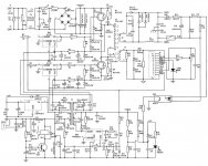
SONGSHI inverter up to 6.4kW.
www.platan.ru/news/news1294-.html
Just to have an idea how it's done cheap way. $50 retail
www.platan.ru/news/news1294-.html
Just to have an idea how it's done cheap way. $50 retail
Attachments
Last edited:
assymetric bridge, or two interleaved? you mean paralled H-Bridge?
Thanx Alex but i think such circuit max output power is 1k as it's paralled flyback as i think, but on the site you provided i found MMA welding machines up to 200A i shall paralle 2 for about at least 300A? and also what is that MMA? is it like TIG or what?
Thanx Alex but i think such circuit max output power is 1k as it's paralled flyback as i think, but on the site you provided i found MMA welding machines up to 200A i shall paralle 2 for about at least 300A? and also what is that MMA? is it like TIG or what?
MMA is manual Metal Arc, just another name for SMAW which requires a constant current power supply like TIG. Flyback is one way to get constant current, PWM and leakage inductance is another. The circuit shows an AC machine, the only way to parallel them is to sync the oscillators and make sure the phasing is correct.
it's not a problem to supply constant 220V supply rail for the welding macheine The line is industerial and can handel 100A Load with no magor voltage drop but to be clear what you mean by constant current? i know constant voltage (Regulation) but constant current? isn't that the same? according to the relation between voltage and current?
also isn't voltage go to near 0 in short circuit when welding start and increase to supcific value when the arc start according to arc lentgh and welding wire diameter?
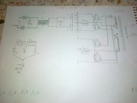
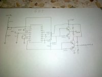
also can't i paralle as many H-Bridge as i want to gain the amps i want?, whatever method i use AC/DC? as in the drawing i posted above?
and last thing? is there any diffrance in welding using AC or DC? and also between regulated 24V or Open circuit 80V? isn't all that cases can weld all metal types if required current applayed?
also isn't voltage go to near 0 in short circuit when welding start and increase to supcific value when the arc start according to arc lentgh and welding wire diameter?
also can't i paralle as many H-Bridge as i want to gain the amps i want?, whatever method i use AC/DC? as in the drawing i posted above?
and last thing? is there any diffrance in welding using AC or DC? and also between regulated 24V or Open circuit 80V? isn't all that cases can weld all metal types if required current applayed?
(Regulation) but constant current? isn't that the same? according to the relation between voltage and current?
100A supply should be fine with a line reactor optional.
With constant current regulation the current does not change between short circuit and normal arc voltage, most welders are not true constant current, they have a slope, One of my welders has adjustable slope (arc force).
If you parallel AC machines like in the circuit and the oscillators are not synchronised something will fail. DC machines can be paralleled easilyalso can't i paralle as many H-Bridge as i want to gain the amps i want?, whatever method i use AC/DC? as in the drawing i posted above?
and last thing? is there any diffrance in welding using AC or DC? and also between regulated 24V or Open circuit 80V? isn't all that cases can weld all metal types if required current applayed?
The difference between AC and DC welders is DC put 2/3rd of the heat into the positive and 1/3 into the negative and the arc is affected by magnetic fields. Sophisticated TIG welders are AC with adjustable +/- duty cycle making it possible to change the heat input ratio just by turning a knob.
For a TIG 24V will be unusable, the arc will be almost impossible to start and the current slope will be extreme making the arc very unstable and the arc current extremely sensitive to arc length
redfox, I suggest that unless you are pretty damn good with switchmodes then you are going to experience many hassles with parts and performance and emi, and wouldn't be allowed to legally operate the welder due to emi, or let anyone else operate it due to safety. It's a daunting task even for an experienced engineer.
Tim
Tim
thanks all, and trobbins, don't worry i think running in low freq will solve emi proble with some filters and snubbers, also i thing i'll do it using H-bridge and TL594, it's for personal and local use so i think there will be no problem, thanks all, and i'll be greatfull if any one wanna to help with any info
thanks all
thanks all
- Status
- This old topic is closed. If you want to reopen this topic, contact a moderator using the "Report Post" button.
- Home
- Amplifiers
- Power Supplies
- Help About 8KW Full Bridge SMPS