thanks Andrew /Keantoken,
Yes, it was the sch. that mislead. Its should be similar to the LM317/337 that I did a while ago.
I am getting some boards made for myself and for anyone who is interested, if I may have Keantoken's permission.
regards
Prasi
Yes, it was the sch. that mislead. Its should be similar to the LM317/337 that I did a while ago.
I am getting some boards made for myself and for anyone who is interested, if I may have Keantoken's permission.
regards
Prasi
Attachments
Jeez, Andrew - the layout is wrong - God has spoken - you're sent down for 20 years - you've failed - you're out!
Perhaps you could express your alterations in a more positive, diyAudio way - simply indicate where he might be able to improve the design, in your opinion, to achieve a better result - it called 'encouragement'.
Now, I might be mistaken but the 78** and 79** regs don't offer a uniform impedance across the freq and power range and also aren't low noise across the same range either, if I remember correctly, yes?
For an amplifier like the HPA-1, this way is (IMO, again) a preferable alternative even if the figures indicate otherwise - some headphone amps do use regulators last with good results, but I find there's a better sound with the C-Mx and K-Mx on the output -
Like a lot of things to do with headamps/phones, you have to try it out to find which one suits your 'taste'
You'll note that there has been no/little mention of capacitor selection here yet - that'll produce some prejudices, no doubt - early days ...
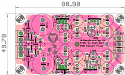
That layout is wrong.
The Centre tap (CT) goes to the junction between the first two smoothing capacitors.
I think I need my sleep. doing two layouts (this PSU on one side and a 500W subwoofer amp on the other ) simultaneously I seem to be making lot of errors.
forgot C1+ existed
 .
.Prasi,
your schematic is going to mislead you into making connections in the wrong places.
The centre tap of the transformer must connect to the junction between C1+ and C1-
................
Good catch. The input C grounds form a big transmission loop for rectifier pulses..................
thanks Andrew /Keantoken,
Yes, it was the sch. that mislead. Its should be similar to the LM317/337 that I did a while ago.
.................
That layout is wrong.
The Centre tap (CT) goes to the junction between the first two smoothing capacitors.
I did !Jeez, Andrew - the layout is wrong - God has spoken - you're sent down for 20 years - you've failed - you're out!
Perhaps you could express your alterations in a more positive, diyAudio way - simply indicate where he might be able to improve the design, in your opinion, to achieve a better result - it called 'encouragement'.....................
both Prasi and KeanT acknowledged that the schematic is misleading. In that first post I described that the CT must go to the first smoothing capacitors (named C1+ & C1-). KeanT then goes on to describe the problems as aerial loops emitting EMI.
Last edited:
Coming to jameshillj's question,
which would work better in the upstream of Keantoken's K-Mult here (just opinions mind you)
1. LM78XX/79XX
2. LM317/337
3. none of the above but something thats entirely made of discrete components like Apex class-A pre-amp PSU?
4. shunt regulators?
May be a bit late to ask the question, as I have too far progressed in layout.
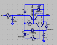
Try this.
Can't get 2SA1930 or TTA004B could you give an alternative?
TIA
Felipe
Attachments
- Home
- Amplifiers
- Power Supplies
- Keantoken's CFP cap multiplier