Hi ben, should this test be done before rectification or after ?
Should I measure voltage drop due to increased current in AC mode or after rectification in dc mode ?
In order to test the transformer and plot it`s response you measure the ac voltage off the secondary first at no load and then gradually increasing the current to about 15%, noting the current and voltage at each load.
the resulting graph will show the point at which the transformer starts to hold it`s own.
this point should be set as the minimal steady load.
If you measure after the rectifires while the rest of the supply is connected you won`t see the secondery voltage below the filter capacitors charge state.
Last edited:
Well in this vein there are several things that could be explored:
1: Resistive loading at 10%
2: Capacitive loading at 10%
3: Capacitive loading of 10% at the 3rd harmonic (1/3 the capacitance).
Knowing which one worked best would tell us exactly what the problem is.
By worked best: Is it sounding best or measuring best?
I have used both resistive and capacitive loading - best listening results with capacitive loading.
At one point of time I had help when changing capacitor values.
The result was two different values as optimal - as the two of us had different references
")
The transformer's performance as a power source doesn't seem to be affected by this enough to change the measurements of the final circuit, except perhaps efficiency. The main difference for me was the audible one as well.
My experience was that different values yielded different sonic effects maybe, but the most important effect was the difference between having a cap or not. The bigger the cap the better, but I never got over 4.7uF because I didn't have any bigger caps.
The cap itself may resonate with the transformer inductance. Mine resonates somewhere around 1KHz. This can be damped with a 22R or so series resistor, but I found it always sounded best with no resistor.
I think that beyond choosing a large enough cap at all, tweaking the size by listening will yield subjective results, not because it's inaudible, but because the effect of the resonance will be heard musically in different ways by different people. So it makes sense to me that you and your friend would come to different conclusions. You may try adding the 22R resistor.
Hello Kean
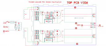
I am now building a kmultiplier for my folded simplistic.
The 36Vac TX will output 51Vdc after rectification and the smoothing cap is 15000uF so if I use your circuit as per the pdf with stock values I will get a 1,2 amp inrush.... no good.
Can I use 1000uF for C1 (instead of 820uF) and increase R8 to 1500 ohm (instead of 680r) to reduce inrush current to an acceptable 470mA ?

You may check the value of the first capacitor 330uF. It may be too low. The K-Multiplier can be tuned to have various input ripples. If the ripples are too high for what it is tuned for then the KM will not be able to smooth out the ripples. I used 6800uF or something as the minimum for 300mA load and a 1.3V drop, or somthing like that. You may scale these numbers. For an example, if you have 100mA load, you can reduce the cap to 2700uF, etc. But unless your load is very small 300uF may be insufficient.
Also, if you are not looking for the absolute minimal voltage drop, you can increase the 1N4007, as in Keantoken's original specification, you should use 3 x 1N4007 in series. If you really want to use a single 1N4007, you will need to increase the 1k resistor to 6k8 or something.
On the other hand, the output should usually not require a capacitor as large as 15000uF, because the KM should be fast enough to supply to the load. I think 1500uF should work very fine.
Good luck.
Bill
I see 3x 1N4148 in series, which is correct.
Other than that, Bill has plenty of experience with the Kmultipliers sonically, so his advice is a good bet.
I'm guessing those 15mF caps are split-film, in which case they should be very good at filtering noise. If they are ordinary caps, I'd agree that 15mF might be overkill. I'm curious if the slit-foil lytic makes it worth doing however.
Last edited:
AudioCap.com.au has a BHC 1100uF/63V Slit Foil available - not small, at 30mm dia x 45mm long or cheap at 7 GBP+ but excellent caps for audio, particularly mids/tops - a rather different 'sound' to the also excellent Jensen 4Ps, but similar to the 'T-Network' caps - I've not seen the 'T-Ns' available at the lower value than the 6800uF, but maybe other vendors ...
For simple ccts such as Followers, single gain stages, etc the cap on the KM output has a dramatic effect, and even buried in front of a shunt reg, it still makes a difference - not sure about complicated ccts
For simple ccts such as Followers, single gain stages, etc the cap on the KM output has a dramatic effect, and even buried in front of a shunt reg, it still makes a difference - not sure about complicated ccts
Now following Bill's pitch, I placed the kmultipliers after the 10000u smoothing caps, followed by small 470u Silmics.
Powering the folded simplistic immediately brought very good results. Smooth rendition of low level detail enhances stereo soundstage presentation.
One issue remains... I have low level hum that is not present when using a "normal" psu.... maybe the 1.7V drop is too much for this implementation.... I get a very small margin to power the V12R shunts because I am using my bench 30vac psu TX ....
- Home
- Amplifiers
- Power Supplies
- Keantoken's CFP cap multiplier