I can work on it, but I've run out of 2SC5171/A1930, and I've only got a few BC3x7-40 (OnSemi) left. If someone can send me some of these I'd be really grateful, but otherwise I can't say when I'll be able to work on improvements to the Kmultiplier, and other things.
If you are curious whether devices like the 2SB649/D669 or BD140/139 or whatnot will work, I'd be glad to test them if you can send some my way. Note that the BD140/139 are different depending on which manufacturer. If you send me something, be sure to say what company it came from (as well as retailer) otherwise the results may be deceptive.
If you are curious whether devices like the 2SB649/D669 or BD140/139 or whatnot will work, I'd be glad to test them if you can send some my way. Note that the BD140/139 are different depending on which manufacturer. If you send me something, be sure to say what company it came from (as well as retailer) otherwise the results may be deceptive.
I can work on it, but I've run out of 2SC5171/A1930, and I've only got a few BC3x7-40 (OnSemi) left.
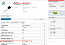
For x=3 , Mouser can send you twelve thousand of them, image below.
They also have 4,500 2SC5171's from Toshiba, and 2,600 2SA1930's from Toshiba.
Mouser ships from Ft. Worth, Texas so the postage ought to be inexpensive.
Attachments
Last edited:
This is the result found when 13 regulators of different manufacturers (or designs which have appeared in DIY circles via The Audio Amateur or Web) (The outlier is the Burson, or the Euphonic Regulator. The Linear Tech off the shelf devices are very,very good.
Later, an observation was presented that the harmonics a regulator can impress on the supply rails played a role in the subjective listening test. The simulations don't exactly replicate reality, but they come close when the devices were checked out using the AP Test Set.
I've ordered the parts to look at the K-Multiplier with the AP Test Set, In the interim here's an FFT simulation of the K-Multiplier as it appears on the web (red), the 820 uF cap on its own (yellow) and the Jung regulator with AD825 error amp. All were loaded the same, and injected with a 20mA perturbation current:
An externally hosted image should be here but it was not working when we last tested it.
Folks are throwing regulators our way for another taste-test.
That is very interesting. I guess that you might find it similar to the Teddy reg, because the KM is not a regulator and it does not regulate. On the other hand, the KM output has lower impedance than the Teddy.
The reason I can use the KM successfully is because the KM doesn't mind any capacitors (low ESR) and any amount of capacitance at its output therefore I can use it safely without worrying about the output inductance and decoupling capacitance forming resonances. The absolute vast majority of the regulators would fail this test.
In other words, the way I expect KM to work is to have a huge amount of capacitance at its output (currently at 4 x 2,2000uF Rubycon ZL with Z=0.015R each at 100kHz) to provide a low impedance at high frequencies.
If you are going to test the KM performance, I suggest puting a large amount of low ESR capacitance at the output of KM, to make your comparison fair, as I see this is the way the KM should work. It is also important to draw at least 100mA current at the KM's output to make your test result meaningful.
Last edited:
Yes, it needs an input cap. I should have added that to the schematic.
2SA1930/C5171 is important for PSRR. Any other choice is a gamble.
looks like I was lucky when I mounted bridge and smoothing caps close, together with multiplier
Maybe so. I always assumed an input cap would be used, so I haven't tested it much without one. Source inductance can cause most regulators to oscillate. I know why this is, but I don't know if I can eliminate that problem entirely and still have a simple circuit. WELL, the simplest fix is an input cap... Need I say more?
With an extra transistor and a few diodes, I can extend PSRR to over 80db I think. I would need another transistor to improve output impedance but that may not really be desirable.
With an extra transistor and a few diodes, I can extend PSRR to over 80db I think. I would need another transistor to improve output impedance but that may not really be desirable.
I think load regulation is what we need while line rejection is NOT important at all, explained below.
If we use a LM317/337 as pre-regs, which give 60dB+ line rejection, combined with the KM we have over 120dB line rejection. That is before the load, which would have another 60dB to 120dB rejection for an opamp. I see no reason to have any more.
However, more load regulation is needed, because the LM317/337 or the KM have around 30-55dB load regulation only.
Note that line rejection is accumulative. So we can cascade two stages and double the amount of line rejection.
However, load regulation is NOT accumulative. So we really have 30 - 55dB load regulation only, and the rest relies on the mercy of the PSRR of the load, and for an average opamp, it may be 60dB at 20kHz.
over what range of frequencies?.................If we use a LM317/337 as pre-regs, which give 60dB+ line rejection, ..................
If the reg let's through most of the HF stuff, then the next reg will let through most of that same HF stuff.
True but the over all level of hf would be lower with the shape of the PSRR curve being about the same . The fact that the curve is not linear in to say 200k is to me more of a problem than the exact level in the range if say less than -80db .over what range of frequencies?
If the reg let's through most of the HF stuff, then the next reg will let through most of that same HF stuff.
How many extra effective inches of output inductance is too much?
Safe bet is two to three inches while achieving 120dB PSRR.
I learnt it the hard way and found that long wires to the load from a regulator really destroyed the sound.
over what range of frequencies?
If the reg let's through most of the HF stuff, then the next reg will let through most of that same HF stuff.
What is why I always prefer having some LRC to get rid of the junks above 100kHz. With LRC you can easily get 120dB above 100kHz.
...120dB above 100kHz......
.... effect at the output of a power amp........
would that improve/increase stability of power amp ?
Most amp designs lavishly pile on the RF/ultrasonic loading to one stage, so there is a lot of damage even a small ultrasonic/RF signal might do. Very low-THD amps will probably suffer the most, relatively.
So high PSRR at 100KHz probably isn't a bad idea, as long as your circuit is already well-shielded from stray fields.
So high PSRR at 100KHz probably isn't a bad idea, as long as your circuit is already well-shielded from stray fields.
Before my amp was finished I had found a better design. This repeated 5 times.
Only now do I just barely have everything I may need to get something road-worthy. And that will wait until I have something that sounds as good as it's specs.
Each time I find a better design I have realized others have done it to some extent already. However many of these designs are nothing more than simulation. We have the knowledge to advance the state of audio amplifiers - we just need to apply it.
Hi Keantoken
Is the schematic in post 329 the final final schemo? Is there ANYTHING else to add to the circuit such as caps on the front end?
I am going to do a ps for the front end + VAS of an amp and I want to make sure that I am in the right ball park to make it right the first time.
Thanks for all your work and for sharing it with the forum.
Thanks
- Home
- Amplifiers
- Power Supplies
- Keantoken's CFP cap multiplier