tinitus, thank for your info.I have additional power supply lytic caps
one at power in, and one at power out
mine are all 470uf/35V..and also the '820uf'
Tinitus, Kean, thank you for suggestionI would suggest at least a small input lytic.
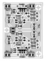
here is my layout
Attachments
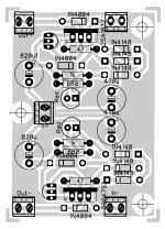
In+ text is missing. Everything looks okay to me.
Another small mistake is that "Ground Input" (at left center, next to the leftmost mounting hole) is labeled In+.
Nice job on the star ground! The 470uF input filter caps are placed at the far end of the raw unregulated In+ and In- PCBtracks, so ((the capacitor's ripple current) x Ztrack) noise is seen by the active circuits. On the other hand, it is a ripple filter after all; it's designed to work well in the face of ripple on raw unregulated In+ and In-.
BTW the TO-92 packaged transistors don't have partnumber labels.
this might not be popular, but for your purposes here, I would recommend just using a linear technologies IC linear reg with simple surrounding circuit. such as the LT1764A or LT1963A. the ICs really are superb, the guys at linear really know what they are on about and the datasheets and app notes are very comprehensive.
This is the result found when 13 regulators of different manufacturers (or designs which have appeared in DIY circles via The Audio Amateur or Web) (The outlier is the Burson, or the Euphonic Regulator
") . The Linear Tech off the shelf devices are very,very good.
. The Linear Tech off the shelf devices are very,very good. Later, an observation was presented that the harmonics a regulator can impress on the supply rails played a role in the subjective listening test. The simulations don't exactly replicate reality, but they come close when the devices were checked out using the AP Test Set.
I've ordered the parts to look at the K-Multiplier with the AP Test Set, In the interim here's an FFT simulation of the K-Multiplier as it appears on the web (red), the 820 uF cap on its own (yellow) and the Jung regulator with AD825 error amp. All were loaded the same, and injected with a 20mA perturbation current:
An externally hosted image should be here but it was not working when we last tested it.
Folks are throwing regulators our way for another taste-test.
Fascinating!
I always suspected regulator harmonics had to do with sonics. I've tried a few times in the simulator to come up with a "linear" regulator. I got some interesting things, but I didn't feel they were rugged enough or ready.
I definitely wouldn't consider the Kmultiplier popular though. It only has a few known builders as of yet.
Low harmonic noise can only be a feature in as much as it has relatively no frequency-dependent distortions. It has many other benefits though, so the question is whether those help any?
The Kmultiplier output impedance is inversely proportional to loading except at high currents. At higher currents output impedance nonlinearity decreases. My Kmultiplier page gives measured figures for various load currents. Do you have plans for tackling this? I would make tests both in the "proportional region" and with near max loading, since the two are different from a harmonic perspective. That is, if anyone really wants to know.
Anybody tried using this with any of the following ?
1 - Regulator before KM
2 - Regulator after KM
3 - Both the above
If so, what were/are your results ?
If not ......
I built the K-Multiplier when it was first invented. Initially there was a bug in the circuit - the inrush current distroyed the driver. After Keantoken fixed that bug, it work relieably without any problems for me.
I found putting a small choke in a CLRC filter before the pre-reg / reg works very well. It gives a very obvious sonic improvement.
Putting the KM in front of the LM317/337, separated via a small LRC filter, further enhances the sound comparing to the LM317/337 alone. The difference was audible.
When I first tried putting the KM after the LM317/337, separated via a small LRC filter, it did not work well. Then I realised my mistake - The KM needs about 100mA current draw in order to provide low output impedance. So I put a dummy 5W resistor at the output to draw more current, and shortened the wires going from the KM to the load. This improved the sound substantially.
I think the LM317/337 output is nosier than the KM so LM317/337 - CLRC - KM should work better than KM - CLRC - LM317/337. Further more, the LM317/337 output is a lot more inductive therefore can create resonant peaks with large or low ESR capacitors, while the KM would allow you to put any low ESR capacitors at its output without resonances (taking out the track inductance and local high Q bypass caps out of the equation).
On the other hand, the standard KM is not a regulator therefore it does not regulate its output. Therefore, load regulation of the LM317/337 at around 60dB is much better than the KM (with large output capacitance) at around 35dB below around 1kHz. From 1kHz to 10kHz, the LM317/337 would have some resonant peaks when working with large output capacitors in this region, so the performance is more or less in line with the KM. Above 10kHz, the KM would work better because the decoupling and bypass capacitors are more effective, without any impedance peaks formed with the output inductance of the active devices.
So which one is better depends on your load. My load is active filter / crossover circuits running opa627 opamps, which have 120dB PSRR below 1kHz, so using KM as the post reg works better for me.
If you ask Keantoken for a Super KMR which improves load regulation from 35dB of the standard KM to about 58dB or so then you would definitely put the KMR as the post reg.
Regards,
Bill
On the LT regs:
I'm looking at the datasheet, and they are comparable in some ways, but they have worse PSRR and worse transient response. They are clearly very high feedback devices with transient limitations and compromised PSRR. The Kmultipliers have good PSRR to 100KHz.
This however appears to be excellent, and may be better than the Kmultipliers:
http://www.ti.com/lit/ds/symlink/tps7a4700.pdf
This one appears to be good and might work as a drop-in replacement for the Kmultipliers if regulation were desired. It is designed to be stable with any capacitance at the output and yet it is fast and has high PSRR to 100KHz and beyond just like the KM. The only difference would be it may have lower output impedance depending on the application, and this may turn it into a high-Q inductor to resonate with low-ESR lytics.
However I didn't find an equivalent negative counter part. I found this:
http://www.ti.com/lit/gpn/tps7a3301
It has worse transient response and creates a lot of peaks at the output. It isn't stable with all caps. So it would not behave like the Kmultiplier and may be suboptimal simply because it will exaggerate the Q of the rail wiring.
I have some super-KM ideas that might compete with the low Zout of these regs without losing the good PSRR. The question is, is it worth the extra complexity and why should I compete with TI? Well actually, I guess I do have one really good trick I haven't shown yet.
So, does an improved KM matter to anyone?
Yes indeed it would, very interesting, altho this cct in front of a Salas shunt reg works very well indeed and saves a lot of 'drama' with diodes, snubbers and compatible cap combinations in the raw supply section.
Also, if you would like to revisit the device, a higher current cct for classA power amps like the basic F5 amp, for example, that draw about 1.5A steady and nearly twice this for large transient - basic Fet Cmultipliers work okay for this, but it would be very interesting to see if a "K" version would function in comparison to a 'good' power regulator (that are difficult to get them to "sound right", even with high dissipation).
Also, if you would like to revisit the device, a higher current cct for classA power amps like the basic F5 amp, for example, that draw about 1.5A steady and nearly twice this for large transient - basic Fet Cmultipliers work okay for this, but it would be very interesting to see if a "K" version would function in comparison to a 'good' power regulator (that are difficult to get them to "sound right", even with high dissipation).
I have had the previllage to have a preview of Keantoken's "really good trick" that has not been shown yet, though I have not had the time to study it. It requires about 6 more components per rail. I have not checked on its line rejection figure because that is not what I am interested. Load regulation improved a lot from the standard KM by as much as 20dB. If I could have any wishful thinking I would hope it could still improve by between 5 - 10dB at 100kHz in which case it would make it a super super reg. Even now it is perhaps more than GOOD for me to use it. For opa627, I would have 120dB total combined PSRR from 20Hz to 20kHz, if I could implement some power and ground planes on the circuit board (which is extremely hard. This is something I need to spend time looking into in the near future). For lm4562, it may be just under 110dB though at 20kHz. I am using a mix of opa627 and lm4562 hence the wishful thinking of having another 5-10dB more. But I guess I am now being unrealistic because the KM is very good, and the KMR is excellent by any standard.
I am now collecting parts to build the kmultiplier.
I plan to use it instead of the "usual" 15000uf smoothing cap before salas shunts.
Total current will be between 300 and 600mA depending on the configuration.
I have lots of BC337 so just need some 2SA1930... are there any alternatives to this last one ?
Why did you choose the 1930 ?
I plan to use it instead of the "usual" 15000uf smoothing cap before salas shunts.
Total current will be between 300 and 600mA depending on the configuration.
I have lots of BC337 so just need some 2SA1930... are there any alternatives to this last one ?
Why did you choose the 1930 ?
Thank you everyone,
i'll build mine with this layout.
Hi naf
What is the purpose of the 470u cap ?
Is it on the input ?
I guess I do have one really good trick I haven't shown yet.
So, does an improved KM matter to anyone?
One can never have a regulator that is good enough. The better is always welcome.
For an example, even with the Super KMR, I mentioned that I could achieve 120dB PSRR at 20kHz for the opa627. This assumes that I could come up with power and ground planes and bypass capacitors directly on the opamp power pins. If there are tracks leading to the opamp power pins, the inductance of the tracks can easily lead to the loss of 10-20dB in load regulation from 20kHz to 1MHz, and more beyond that. So the total PSRR may be dropped to only about 100dB at 20kHz, which is good but not brilliant.
In reality, to implement power and ground planes directly covering opamp power pins is extremely difficult, because this may introduce too much input capacitance that can ruin the performance of the opamps. I imagine I could only implement the planes at the outer peripherals, and would still need to use power / ground tracks leading to the opamp power pins.
This suggests that 120dB PSRR for the opa627 is not realistic.
If we had 5-20dB better performance from a regulator then we are closer to the ideal target.
- Home
- Amplifiers
- Power Supplies
- Keantoken's CFP cap multiplier