what you all think about this design?
Conserning cap multiplier section,use 3 x 1N4148 in series for your D8 as shown on web page The K Multiplier.
Hi Kean
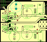
Reworked the layout now using your simplified schemetic. Trying to follow your board layout I included a copper pour connected to GND.... your comments are most welcome here as I do not have enough experience on how to use gnd planes.
Best Ricardo
Reworked the layout now using your simplified schemetic. Trying to follow your board layout I included a copper pour connected to GND.... your comments are most welcome here as I do not have enough experience on how to use gnd planes.
Best Ricardo
Attachments
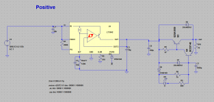
LT3042 output cap as KeantokenCFP
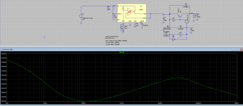
hi guys.Check this out
I might be doing something wrong but the results are very good.
Can someone please verify this.
hi guys.Check this out
I might be doing something wrong but the results are very good.
Can someone please verify this.
Attachments
Reworked the layout now using your simplified schemetic. Trying to follow your board layout I included a copper pour connected to GND.... your comments are most welcome here as I do not have enough experience on how to use gnd planes.
Few here use ground planes, the important thing is to just not create large current loops when small current loops will do. If you can do a good one-sided layout, then using ground planes starts being a good idea. I don't think they are much of an improvement the way you are using them.
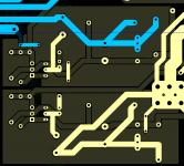
It's hard to figure out your layout without seeing the whole board. And I'm not really in a good position to teach this stuff. If others here can't find flaws with the board, then you will probably be satisfied with it. There is no guarantee that my advice won't just confuse you and cause you to make a worse layout.
Looks reasonable to me. PSRRs add when you put regulators/KMs in series. Of course at some point EMI will cause more noise than is getting through your regulators.
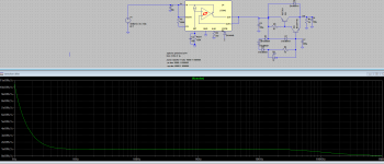
Thanks Kean. I know it is still simulation but if I don't add a Cap after the CFP the output impedence is significantly high. Why is that?
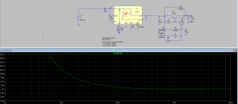
zener follower with CFP
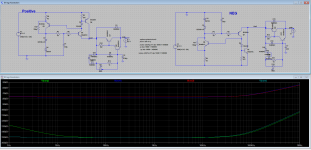
while waiting for a reply I experimented with another design and got this. But for some reason I have to use 10x capacitance to get the same PSRR.
Please get the models from here
http://www.cordellaudio.com/book/Cordell-Models.txt
while waiting for a reply I experimented with another design and got this. But for some reason I have to use 10x capacitance to get the same PSRR.
Please get the models from here
http://www.cordellaudio.com/book/Cordell-Models.txt
Attachments
Last edited:
The amplifier's output Zobel is predominantly an HF load.I am using separated paths for the zobel gnd and other grounds... they will all join star ground on the psu board. Somehow I believe zobel return should not be connected directly to other gnd. Am I wrong ?
In fact I see the zobel as another load to the power amp and as we normally route speaker return to the psu star, I decided to do the same for the zobel.
10ohms+100nF has an F-3dB frequency of 159kHz.
The load presented to the amplifier at this frequency is ~14ohms.
Significant VHF current can only flow through the output Zobel if the impedance at these high frequencies is maintained to a very low level.
This cannot happen if you take the output Zobel route on a tour around the amplifier to tie into some remote star.
The impedance can only be kept low by placing the output Zobel in a short compact LOW LOOP AREA route around the output devices and HF decoupling.
Last edited:
- Home
- Amplifiers
- Power Supplies
- Keantoken's CFP cap multiplier