Nice. It's tall enough to not fit in many places though. I wonder if it could be shortened? I like the idea of replacing 3-terminal regulators with it. ")
However for that I'd make it zener regulated so people don't try to use them in a circuit that needs a constant voltage.
I would add decoupling to the input and output, because we don't know what it would be plugged into.
However for that I'd make it zener regulated so people don't try to use them in a circuit that needs a constant voltage.
I would add decoupling to the input and output, because we don't know what it would be plugged into.
like regulators, decoupling caps are to place externally and the user choose the capacitor value and type (to ground).
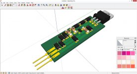
The PCB fits on a Fischer Elektronik SK104.
Direct Heated Tubes needs a constant voltage (300B +5VDC) done by, rectifiers, caps, pre-regulator +5VDC+1.8VDC, caps, and K-Multiplier to achieve the needed +5VDC for the first pole of the heather; connect the current sink (2SC5171 + BC817-40 + 1k0 to +6.8VDC + 0.6V/1.2A = 0.5R@2W/1%/2512 resistor) on the second pole ... in french, le tour est joué!
There is here a Rob Coleman DHT thread...
For bias current, it's diminishing returns after 100mA, and I'd set it low at 25mA so it's not wasting 1/4 of its power out of the box. At 25mA the emitter resistor for the current sink will dissipate only 17mW, so don't need large resistors here. Add some vias for users to solder in their own sink preference?
If the current sink feed resistor is 56k it will work up to 100V (resistor will be hot though, how hot should we let resistors get for longevity?).
If the current sink feed resistor is 56k it will work up to 100V (resistor will be hot though, how hot should we let resistors get for longevity?).
I builde K Multiplier but I can not find 2sa1930 and 2sc5171. So I use Bd140, bd139 instead. It works with no load and 1.2k (around 20ma load) as load. However when connect to c4200uF and salas shunt reg which draw 140 ma, led at k multiplier turn on and voltage drop is high(6v). Where should I look for to solve this.
Assuming you haven't made any wiring errors, do you have lytics right at the input and output?
The BD139 is a different transistor depending on who you get it from, some versions are slow. If you use the wrong transistor for this position it can cause oscillation. Which transistors do you have that you could use here?
The BD139 is a different transistor depending on who you get it from, some versions are slow. If you use the wrong transistor for this position it can cause oscillation. Which transistors do you have that you could use here?
Mouser has both in stock. Shipping to you should be small. RegardsI builde K Multiplier but I can not find 2sa1930 and 2sc5171. So I use Bd140, bd139 instead. It works with no load and 1.2k (around 20ma load) as load. However when connect to c4200uF and salas shunt reg which draw 140 ma, led at k multiplier turn on and voltage drop is high(6v). Where should I look for to solve this.
Assuming you haven't made any wiring errors, do you have lytics right at the input and output?
The BD139 is a different transistor depending on who you get it from, some versions are slow. If you use the wrong transistor for this position it can cause oscillation. Which transistors do you have that you could use here?
I have 4200uF electrolytic at the input and output. Is it too much on the output?
For Transistor, I can have
PNP MJE2955T, TIP32C, TIP127, TIP42C.
NPN MJE3055, TIP31C, TIP122, TIP41C.
All of those are too slow, so I think BD139/140 are your only option. Others have successfully used them.
I'd go through the troubleshooting section in the link in my signature and make sure it's not a wiring problem and that all the transistors are healthy. I don't think 4200uF should be a problem.
I'd go through the troubleshooting section in the link in my signature and make sure it's not a wiring problem and that all the transistors are healthy. I don't think 4200uF should be a problem.
I want to try this in a preamp build and had a few questions. IS there a limit on how much capacitance we should put in front of this reg. Also, If I wanted to implement the psu in a aseperate box from the main boards, does the length of umbilical chord present any issues? i ask only because of the statement about inductance on your blog.
There is no limit to the capacitance you can put in front of it. As long as there are lytics at the input and output, umbilicals will not cause the circuit any problems, but the inductance of the umbilicals will resonate with whatever reservoir scheme you have. Umbilicals that are not too thick will have enough resistance to damp this resonance.
You couldn't be more right about that.
I have had people build the KM for only the filtering purpose however. I'd say if the output of the Kmultiplier will directly influence the rails of the circuit (IE no extra power circuit between KM and load), then you should put it AT the given circuit, to take advantage of the low output impedance.
I have had people build the KM for only the filtering purpose however. I'd say if the output of the Kmultiplier will directly influence the rails of the circuit (IE no extra power circuit between KM and load), then you should put it AT the given circuit, to take advantage of the low output impedance.
- Home
- Amplifiers
- Power Supplies
- Keantoken's CFP cap multiplier