Dear all....
i am working on this very simple transistorised circuit, but results are disappointing. The schematic is attached.
The problem is, inspite of refrence voltage of TL-431 not being 2.5v, TRANSISTOR Q1 turns on. I dont understand how. I have used MCT2E as optocoupler and a 15V zenner for limiting the collector emitter voltage for MCT2E as well as for TL-431.
Please let me know the flaw in the design.
vasu
Attachments
Hi Vasu, since no one else has chimed in I thought I'd add my 2c worth ")
I don't really understand your circuit or it's intention, but a quick look at the datasheet for the TL431 makes me wonder whether you are implementing it correctly.
The values of the resistors you have chosen would appear to mean it is set up for 55V (if I'm reading the datasheet correctly) which is clearly outside the specs, and I can't see that being what you would want on the input to the optocoupler. from what I can see the optocoupler will always be turned on, which would result in Q1 being turned on.
As I said I don't actually understand what the circuit is supposed to do so maybe my comments are not helpful, but I thought I'd post anyway Perhaps you can explain how you think the circuit should be working, often I find that in explaining to someone else we realise the error ourselves.
Tony.
I don't really understand your circuit or it's intention, but a quick look at the datasheet for the TL431 makes me wonder whether you are implementing it correctly.
The values of the resistors you have chosen would appear to mean it is set up for 55V (if I'm reading the datasheet correctly) which is clearly outside the specs, and I can't see that being what you would want on the input to the optocoupler. from what I can see the optocoupler will always be turned on, which would result in Q1 being turned on.
As I said I don't actually understand what the circuit is supposed to do so maybe my comments are not helpful, but I thought I'd post anyway
Perhaps you can explain how you think the circuit should be working, often I find that in explaining to someone else we realise the error ourselves. Tony.
Attachments
Hi wintermute,
Glad you replied, The circuit as you have understood is supposed to break the relay contact when the input voltage reaches, 55.2V. And i have biased both TL-431 and MCT2E with 15V(zenner in the circuit) so that was no the issue, and as you mentioned, the problem was exactly the same, the Q1 transistor remained on in all conditions cause the optocoupler was always pushing in some current.
Thus i made a small change in the circuit. I added a 750E to the emitter of optocoupler and the grounded it.
That has helped.
Anyways thanks for your advice.
Take care
vasu
OK glad to hear you have sorted out the problem and thanks for the explanation. I get it now, if the voltage is below the 55.2V threshold then theoretically there should be no current flowing through the TL431 and the opto coupler shouldn't turn on. If the voltage goes above, then the TL431 starts shunting turning on the optocoupler, which turns on Q1 removing the bias for Q2.
Only thing I'm still unsure on though is how the TL431 is going to see the 55.2V (I admittedly haven't read the whole datasheet, and my electronics understanding is not at a very high level , but I would have thought it needed to be across the supply, not fed from the zenner.... Have you tested that it really does turn off the relay if the voltage goes above 55.2V?
Tony.
and thanks for the explanation. I get it now, if the voltage is below the 55.2V threshold then theoretically there should be no current flowing through the TL431 and the opto coupler shouldn't turn on. If the voltage goes above, then the TL431 starts shunting turning on the optocoupler, which turns on Q1 removing the bias for Q2. Only thing I'm still unsure on though is how the TL431 is going to see the 55.2V (I admittedly haven't read the whole datasheet, and my electronics understanding is not at a very high level
, but I would have thought it needed to be across the supply, not fed from the zenner.... Have you tested that it really does turn off the relay if the voltage goes above 55.2V?Tony.
Hi..
You have got the major part of the logic.
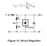
The TL-431(see the datasheet or application note), is a voltage referance diode. It has reference voltage of 2.5v, so if the the varisble wing of this diode is biased with 2.5 it starts to conduct. Thus, i have used a voltage divider circuit to bias the pin-3 of tl-431 to 2.5V,when the input voltage is 55.2V, the rest of the circuit you have farely understood.
As far as connecting it to the supply is concerned, tl-431 doesnt conduct at such high supply, max 30V(confirm from the datasheet).
also mct2E's collector emitter voltage is 30V, thus i have used zenner to bias it.
Hope i have made things bit clear for you.
Keep in touch
vasu
You have got the major part of the logic.
The TL-431(see the datasheet or application note), is a voltage referance diode. It has reference voltage of 2.5v, so if the the varisble wing of this diode is biased with 2.5 it starts to conduct. Thus, i have used a voltage divider circuit to bias the pin-3 of tl-431 to 2.5V,when the input voltage is 55.2V, the rest of the circuit you have farely understood.
As far as connecting it to the supply is concerned, tl-431 doesnt conduct at such high supply, max 30V(confirm from the datasheet).
also mct2E's collector emitter voltage is 30V, thus i have used zenner to bias it.
Hope i have made things bit clear for you.
Keep in touch
vasu
Last edited:
- Status
- This old topic is closed. If you want to reopen this topic, contact a moderator using the "Report Post" button.
- Home
- Amplifiers
- Power Supplies
- simple design not working.