I'm building a phono amp and need + and - 15v sources.
I'm trying to tap into an old realistic amp SA-155.
Got two red wires from the transformer that go to posts and read 15v AC. Yellow center tap goes to switch.
When I take these out to a full wave rectifier(one unit that I know is ok). and then to smoothing caps I get 21v on the plus side and 42v on the neg. side.
I'm using jumpers to experiment and I'm pretty sure all is wired correctly. This is all using chassis ground as a reference and all grounds tied together.
Thought I had found the perfect source to build a supply using 78 and 7915.
Maybe disconnect transformer from circuit board and try again?
Confused
When I take these out to a full wave rectifier(one unit that I know is ok). and then to smoothing caps I get 21v on the plus side and 42v on the neg. side.
This sounds all wrong.
You should have 2 full-wave bridges if you want to develop positive and negative supplies, with the positive output from one tied to the negative output of the other and the junction of these tied to ground.
Draw a schematic of what you have, scan or photograph it in reasonable quality and post it.
w
I'm building a phono amp and need + and - 15v sources.
A center tapped 15V transformer is simply not going to work. For the small amount of current you need Antek will sell you exactly what you need for $10.
Antek - AN-0118
The AN-0118 looks to be about right.
It looks like from your measurements the center tap was connected to something other than ground. But it does not mater if the goal is a dual +15/-15 V supply
Good link. Thanks for that helpful viewpoint.
You can tell I'm kind of a newbie so I appreciate the advice.
So a center tap won't work? I ask that for my education.
I'm posting a couple pics so you can maybe get a clearer idea what I'm saying.
And the center tap(or center wire) is connected to off/on switch board but no voltage on it.
Thanks
Only one pic would upload. I even resized others but maybe this will do.
Attachments
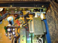
Well the center tap is the return for both your new supplies, since it's not grounded but switched that could be one of your problems here.
I would disconnect the 2 reds since they might be connected to 2 rectifiers onboard, and use centertap for all returns and measurements. Otherwise 2x15VAC s/b near perfect for +/-15 volt regulators using one full wave bridge (ie 4 rectifiers)
I would disconnect the 2 reds since they might be connected to 2 rectifiers onboard, and use centertap for all returns and measurements. Otherwise 2x15VAC s/b near perfect for +/-15 volt regulators using one full wave bridge (ie 4 rectifiers)
Well the center tap is the return for both your new supplies, since it's not grounded but switched that could be one of your problems here.
I would disconnect the 2 reds since they might be connected to 2 rectifiers onboard, and use centertap for all returns and measurements. Otherwise 2x15VAC s/b near perfect for +/-15 volt regulators using one full wave bridge (ie 4 rectifiers)
Good diagnosis.
Reds are connected to on board bridge. Yellow was connected to off/on switch.
I unsoldered yellow and configured it as zero volt line and perfect. 22v+ and-22 with full wave. Should work nice for regulated 15v I hope.
Thanks again
Good link. Thanks for that helpful viewpoint.
You can tell I'm kind of a newbie so I appreciate the advice.
So a center tap won't work? I ask that for my education.
A center tapped transformer would work fine. But an 18V CT one will not
18 V CT means there are 18 volts across the full secondary and 9 volts from the CT to either end. An 18V CT transformer is sometimes called 9-0-9 volts and I think this way is more informative. If you could find a 36 CT or 18-0-18 you'd be able to build a +/- 15 volt split supply.
As a rules of thumb rectified DC volts are abut 1.2 times the AC volts from the transformer. It not an exact rule but provides a good start. Then figure the regulator will drop the volts at least by 2V, or 3V to be safer. Work backwards to find the transformers you need. However a CRC filter in front of the regulator can drop voltage too
Might not have been specific in my first post.
Two red wires put out 15vac each.
My apologies.
- Status
- This old topic is closed. If you want to reopen this topic, contact a moderator using the "Report Post" button.
- Home
- Amplifiers
- Power Supplies
- Help need with PS for Idiot