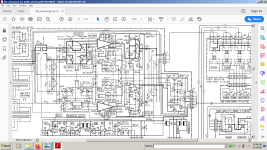
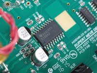
Maybe this will help a bit more .What you see there is not a regular op-amp, is an op-amp that takes about 50ma of idle current and has radiator thins as a power op-amp.
http://f1.hifidiy.net/forum/201612/30/002804vevurcdgfe1tqf33.jpg
http://f1.hifidiy.net/forum/201612/30/002804vevurcdgfe1tqf33.jpg
Attachments
Last edited:
Apparently you did not see that this thread started with a "class A regulator" (shunt regulator),you gotta be kidding...there's no need for any regulator in a class a preamp... ..
not with a regulator for class A preamp.
However - show us a preamp which is not working in "class A" ..
Last edited:
Would you please spell the title of this topic for me , please?Apparently you did not see that this thread started with a "class A regulator" (shunt regulator),
not with a regulator for class A preamp.
However - show us a preamp which is not working in "class A" ..
What does "A-class preamp PSU" mean for you?Please explain your question.
Well...it's not misleading me for sure!I understand that the title is misleading you.
A better thread title would be "Class A PSU for preamp".
See post 1.
not loosing one more minute on this topic!See post 1 and post 3 ( and 4 ) ..
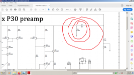
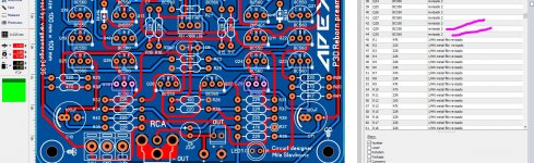
wow! hey I just want it a normal power supply for my hobby I know that the title is misleading this is not a power supply for a class A preamp is a normal type of circuit I think Apex P30 preamp is CFA topology not sure, I made the simulation so far I see that responds really well not till I put it together in real time I just need a simple symmetrical -24V - 0 +24V
Attachments
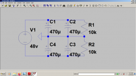
There's a reason why you only have that first order rc decoupling filter on the rails !wow! hey I just want it a normal power supply for my hobby I know that the title is misleading this is not a power supply for a class A preamp is a normal type of circuit I think Apex P30 preamp is CFA topology not sure, I made the simulation so far I see that responds really well not till I put it together in real time I just need a simple symmetrical -24V - 0 +24V
I'd suggerst 7824/7924 regulators before that and just 470...1000uf riple capacitors on the rectifier bridge.
Personally i wouldn't use any regulator at all...just a 48v DC supply and a floating ground done with 4 good capacitors (2 capacitors and a10...27 kohm resistor in parallel on each rail side).
Attachments
Last edited:
If you feel that the sub base frequency reproduction is a bit too thin, you just increase the number of parallel capacitors or their value up to 4700uf per rail, but 1000uf should be more than enough..RNHP is using a 1300v/us slew rate current feedback op-amp ...
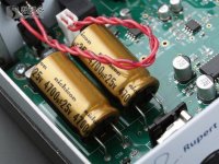
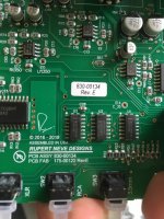
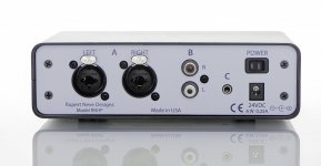
RNHP Headphone Amplifier
I think you can trust this guy! The whole recording world relies on his designs for 50 years!
RNHP Headphone Amplifier
I think you can trust this guy! The whole recording world relies on his designs for 50 years!
Attachments
Last edited:
There's a reason why you only have that first order rc decoupling filter on the rails !
I'd suggerst 7824/7924 regulators before that and just 470...1000uf riple capacitors on the rectifier bridge.
Personally i wouldn't use any regulator at all...just a 48v DC supply and a floating ground done with 4 good capacitors (2 capacitors and a10...27 kohm resistor in parallel on each rail side).
thank you so much for you suggestion I'll do that then
")
Rupert Neve rules !thank you so much for you suggestion I'll do that then
Your preamp doesn't need any regulation at all.Regulation is just for safety reasons as the bc550/560 transistors in the final stage aren't really good there...I'd use bd139 /bd140 instead or at least bc337/bc327 for q29/q30 and ksc1845.ksa992 for q19/q22 and thus any regulation becomes completely useless.
Last edited:
So it's a very basic one!!!...
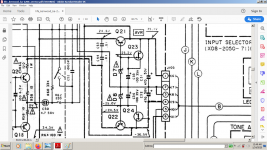
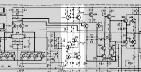
But only because they've exported some of the complexity elsewhere. Take a look at the highlighted part:
Q32 is a CCS for the voltage reference D9 used to control the shunt regulator Q28, which is cascoded by Q24/Q26 and fed by a current mirror Q30/Q34. That's a fairly sophisticated second stage of regulation.
But there's more. The shunt regulator then feeds the cascodes, turning them into quasi series regulators for a third stage of regulation.
This put a smile on my face as I hadn't seen it before and it's a very elegant design -- but basic it's not.
Cheers,
Jeff.
Attachments
Of course they did it! It's done by the Accuphase designers...i'm literally copying their simple block in almost anything i do as it's the best thing i ever saw in audio.But only because they've exported some of the complexity elsewhere.
Cheers,
Jeff.
It's a saying in my country that i don't know exactly how to translate in english, but basically tells that you don't fix a good item with bad parts...
So...the reverse of this saying would be: are you using ultra fancy regulators for low quality audio equipment?
Vargas came with the ideal example of a preamp than needed no regulator at all...yet attached to it also came another ultra fancy regulator when the 10ohm-100uf RC filter would have destroyed any benefit that the fancy regulator would have brought with it which shows that either both designs have real flaws either the regulator was added by someone else.
Last edited:
Sure, but I think that's a valid DIY strategy.
When dropping a floor in my house, I looked up the structural engineering calculations to determine the size I-beam I needed for the suspended floor. However, not being well-versed in the field, I then used something much larger to be sure I hadn't missed anything.
Same thing can apply to audio: if one doesn't know how the PSU will affect the following circuits, one strategy is to make sure it can't. Of course another strategy is to find out, and then only use what's necessary, but that might be over the constructor's current skill level.
Cheers,
Jeff.
Rupert Neve rules !
Your preamp doesn't need any regulation at all.Regulation is just for safety reasons as the bc550/560 transistors in the final stage aren't really good there...I'd use bd139 /bd140 instead or at least bc337/bc327 for q29/q30 and ksc1845.ksa992 for q19/q22 and thus any regulation becomes completely useless.
oh ok I will see if I can make those changes I'm not done with the PCB yet I follow sure is that is the best choice I will go for it
Attachments
- Home
- Amplifiers
- Power Supplies
- A-class Preamp PSU