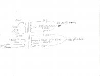
Would a kindly and so inclined member be so generous as to steer this cave man towards a solution. It has been like going through rabbit holes as an ADHD rabbit. I have been in and out of these threads for hours now. I know there are voltage regulator remedies and there are transistor circuit remedies. I am neutral and have no obligations to any camp. I have plenty of heat sink real-estate and so long as it is stable and low noise don't mind things getting hot if they need to. This is my transformer artfully represented below and I have two of them.
My challenge is the Pass F5 amp wants +/-24 volts. I have the iron to meet the specs that it be rated at 6 amps continuous duty, and more than 10 amps peak per channel. My problem is that my toroids start at 24volts before the rectifier. I likely can get by with only one transformer but am open to using both in separate chassis, because this is all over the top any way. But if it really makes sense to use one then one it is.
I know this is a duplicative, redundant, and passive hand holding request, but I am done in and really enjoy cobbling together designs from the schematics of those who know and are willing to lead those who merely solder.
Thanking all in advance. Those offended by such requests need not rub it in. I get it. And when I achieve my EE degree I will repay the kindness ten fold.
Attachments
Would a kindly and so inclined member be so generous as to steer this cave man towards a solution. It has been like going through rabbit holes as an ADHD rabbit. I have been in and out of these threads for hours now. I know there are voltage regulator remedies and there are transistor circuit remedies. I am neutral and have no obligations to any camp. I have plenty of heat sink real-estate and so long as it is stable and low noise don't mind things getting hot if they need to. This is my transformer artfully represented below and I have two of them.
My challenge is the Pass F5 amp wants +/-24 volts. I have the iron to meet the specs that it be rated at 6 amps continuous duty, and more than 10 amps peak per channel. My problem is that my toroids start at 24volts before the rectifier. I likely can get by with only one transformer but am open to using both in separate chassis, because this is all over the top any way. But if it really makes sense to use one then one it is.
I know this is a duplicative, redundant, and passive hand holding request, but I am done in and really enjoy cobbling together designs from the schematics of those who know and are willing to lead those who merely solder.
Thanking all in advance. Those offended by such requests need not rub it in. I get it. And when I achieve my EE degree I will repay the kindness ten fold.
I guess I don't see much of a problem. You'll get something like 27.5 VDC average, after the rectifiers. That's about perfect for regulating down to 24VDC. You could use 5A regulators with power transistor "helpers", to get your higher current limits. There are lots of schematics around, for those. The LM338 datasheet at national.com even shows how to use two or three LM338s to get a 10A or 15A regulator. Linear.com has lots of power supply circuits, too. Their LT1084 is also a 5A regulator. And there's a much cheaper LD1084 5A regulator available from places like mouser.com and digikey.com . Of course, you could just use power transistors and a few other bits and make discrete regulators that could handle more than enough current. You could even select a high-current chip from linear.com and do them as switch-mode supplies, probably with just one chip per side.
Cheers,
Tom
Last edited:
I appreciate your taking the time to detail the options and reasure that this is straight forward. Re-reading my post I did not explain that while I have seen these schematics I have no basis to choose or to really understand the strenghts and vulnerabilities of these designs when used with a Class A Pass F5 amplifier.
Is there some sonic difference between these designs? For instance, when looking for a PS for a headphone amp I found these cute as a button high end switching power supplies that would have been very expensive off the shelf for pennies on the dollar. The spec's would have made any rocket scientist happy. But they are totally unusable in any audio supply. These puppies would reduce a Levinson amp to bargain bin Walmart.
Because I have the opportunity to build what would be optimal I am seeing too many options without enough discussion of the trade offs.There are always trade offs balanced with what is optimal.
Thanks for your interest and support.
This might be slightly off topic, but... Switching power supplies can be great for audio amplifiers. And that makes sense, since it is much easier to filter out, without affecting the audio band, switching frequencies that are far above the audio band than it is to filter out 120Hz or 100Hz that is in the audio band. There are many reports here that claim switchers sound significantly better than linear power supplies. A simple series L and shunt C low-pass filter can get rid of basically all of the high frequencies. Following that with a linear post-regulator can get the ripple+noise down in the hundreds of microvolts or less.
I don't really have any specific answers to your question about the possible sonic differences of using various power supply and regulator topologies. I'm guessing that other factors in the system could easily be far more significant.
However, I do view the power supply as being directly in the signal path. If you think about it, the small input signal is just a sort of "template". And it goes no further than the first amplfication stage's input. The output of any amplification stage comes straight through the power supply, with the small signal input merely attempting to control it.
- Status
- This old topic is closed. If you want to reopen this topic, contact a moderator using the "Report Post" button.