For high current power supply circuits like a fast charger for an EV, could inductors be made by coiling copper tubing? It is cheap, commonly available, and low resistance. They can be cooled by pumping a nonconductive fluid like mineral oil or even air through them and their cross section makes more efficient use of material after accounting for skin effect. They can be painted if insulation is required.
Would the amount of tubing needed to get useful inductances be impractical? What would be the current rating of different sizes of tubing?
For example, a homemade EV charger contains two 150uH, 50A inductors. They cost about $27 each. How many feet of tubing at what minimum size would be needed to make equivalent inductors and how much cheaper would they be? Assume overall size is of little concern, like if the charger is designed to be installed in a garage.
Fluid cooled and tubular coils don't make much sense unless you are dealing with extremely high power (more than a 200A residential service provides) or RF... or maybe you'd be looking for very high power density, but you said you don't care about that. The whole idea of green transportation means that high efficiency figures heavily into the deal across the board, meaning that you'd seek to minimize loss before giving up and simply increasing dissipation capability. $27 bucks for single quantity parts to build a DIY electric car charger seems well in-range, not knowing anything else about your project.
Last edited:
Standard practice in AM tower matching and phasing networks.For high current power supply circuits like a fast charger for an EV, could inductors be made by coiling copper tubing?
It's not my design but you can find it at DIY Open Source EV Charger - Fuel Economy, Hypermiling, EcoModding News and Forum - EcoModder.com .
I'm thinking air core as nothing special would be needed, but other materials can be used if they are easily available to the average DIYer.
And what would the current rating be for 1/4" tubing under passive cooling?
I'm thinking air core as nothing special would be needed, but other materials can be used if they are easily available to the average DIYer.
And what would the current rating be for 1/4" tubing under passive cooling?
This .pdf doc from the ARRL might help, but notice that the air core coils are around 10 to 20 uH:
www.arrl.org/tis/info/pdf/9708033.pdf
www.arrl.org/tis/info/pdf/9708033.pdf
This sort of gives a sanity check, .15 mH, 12 Ga, .032 ohms:
Goertz CF.15 (12 AWG) Copper Foil Inductor from Madisound
Sorry the above is way too small with .032 ohms series R.
I get 1.6 V across it at 50 A, which is 80W; might want to check that.
What's the switching frequency?
Goertz CF.15 (12 AWG) Copper Foil Inductor from Madisound
Sorry the above is way too small with .032 ohms series R.
I get 1.6 V across it at 50 A, which is 80W; might want to check that.
What's the switching frequency?
Last edited:
Copper tubing is good when you want water cooling.
If you don't need to dissipate that much, then air cooled strap is preferred. Solid wire is bad, eddy currents cook it quickly.
Somewhere on CNCzone, a guy was winding an impressively large inductor. I have no clue why it was so large, I think he was building a 10kW induction heater, which would only require a few pounds worth of inductor for a typical buck supply at, say, 50 or 100kHz. Maybe he picked 10 or 5kHz or something else silly slow. In any case, the beast he produced was wound with several hundred feet of 5 mil copper foil, wound around a big stack of U-cores arranged for maximum airgap (that is, U's pointing outward from each side, so it looks like an I-beam).
Tim
An externally hosted image should be here but it was not working when we last tested it.
If you don't need to dissipate that much, then air cooled strap is preferred. Solid wire is bad, eddy currents cook it quickly.
Somewhere on CNCzone, a guy was winding an impressively large inductor. I have no clue why it was so large, I think he was building a 10kW induction heater, which would only require a few pounds worth of inductor for a typical buck supply at, say, 50 or 100kHz. Maybe he picked 10 or 5kHz or something else silly slow. In any case, the beast he produced was wound with several hundred feet of 5 mil copper foil, wound around a big stack of U-cores arranged for maximum airgap (that is, U's pointing outward from each side, so it looks like an I-beam).
Tim
Switching Converter Power Supply Calculator
For 340v input (rectified 240v), 144v output (144v battery pack), and 50A output current, the inductor value required is about 40uH at 20kHz, 24uH at 35kHz, or 17uH at 50kHz. At higher frequencies, an air core inductor does appear to be practical, but I'm not sure if those frequencies are practical for the switching transistors. It's high for regular IGBTs, although high speed IGBTs should handle it fine. Maybe MOSFETs can be used but I remember reading that above 200v and 20A (or something like that), IGBTs are generally a better choice than MOSFETs.
Then go into discontinuous mode as the batteries finish charging and thereby cause the circuit to reduce output current. IIRC, float charging with high current pulses is actually good for lead acid batteries as it helps prevent sulfate buildup.
For example, a homemade EV charger contains two 150uH, 50A inductors. They cost about $27 each. How many feet of tubing at what minimum size would be needed to make equivalent inductors and how much cheaper would they be? Assume overall size is of little concern, like if the charger is designed to be installed in a garage.
Yikes! You might want to reconsider the size issue.
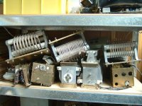
I play with RF stuff; here are a few of my silver plated copper tube coils. The one in the middle is 15.5uH.
Without some hefty shielding, in a 50A SMPS application you'd be running into trouble with any sensitive control electronics nearby (just think of a 150uH 1/4" tube coil......)
Attachments
OK, I just worked out a "practical" 150uH inductor with 1/4" tube.
This will be a single layer air core (you're not going to tightly wind that into a toroid very easilly).
For a adequate air-core inductor, you generally want the length to be between 1 and 2 times the diameter. The required dimensions and turns therefore are:
Diameter = 10"
Length = 15"
Turns = 34
That gives you a turn every 11mm, so no insulation problems.
Big coil!
1 turn on a 10" diameter gives you a circumference of 31.4", so 34 turns requires approximately 1068" = 89' of tube !
Last edited:
You definitely want a Kool-mu or gapped ferrite core for this. GK's example illustrates how large an air core inductor is. The calculator likewise says such a huge coil is unnecessary. Modern IGBTs are quite excellent in the 50kHz range, most have switching times on the order of 200ns max.
The downside to a fairly small inductor is it may need water cooling (ferrite due to just hysteresis, powdered iron due to eddy currents as well). The core can be bathed in water directly, while coated copper strap will also be comfortable with this. Copper tubing can be cooled directly of course, but you get the problem of an unfavorable aspect ratio (big eddy current / proximity effect losses due to the thick coil cooking itself).
Offhand, a 4" o.d. core, #26 mix (that awful yellow/white filter toroid you see in PSUs), is listed as about 600At and 180nH/T^2 at that DC bias. You'll get 12 turns at 50A, or 26.4uH. This is like T400A-26 from Amidon. Core loss will certainly be high enough that you'll need a fan at least, but water flowing over it would be excellent. Water cooling is quite reasonable for a power supply in the 7kW range.
Tim
If your calculations are correct and you only need say 20 to 50 uH then it might be reasonable to do a 2-3 layer, very large air core with perhaps 3/16" tubing.
What were you planning to use for a case? If you build it say in an old PC mini tower there'd be plenty of room for say a 3-4" diameter by 8-10" long 2-3 layer coil. I believe that such a large coil will cool just fine given the large surface area and good air flow. It is an unconventional solution, but it might work just fine. No need for the cost and complexity of water cooling.
On the other hand, you'd only need one of the $27 150 uH coils given your calculations, perhaps even less cost since you don't need the full 150 uH.
20' of tubing wound into an 8" diameter coil yields just over 9 turns. At a spacing of 1/8" between turns, it yields about 18.6uH. Looks like it would be just within reach for a 50kHz switching frequency. Air is virtually lossless as a core material and resistance losses should be small. There might be a more optimal geometry but I'm not sure how to figure it out.
I wonder what's the highest inductance that can be obtained with 20' of tubing with only an air core...
I wonder what's the highest inductance that can be obtained with 20' of tubing with only an air core...
- Status
- This old topic is closed. If you want to reopen this topic, contact a moderator using the "Report Post" button.
- Home
- Amplifiers
- Power Supplies
- high current inductors from copper tubing?