Hi all,
not sure if this thread is the appropriate one, but I found a full set of black V1.1 boards in my drawer including a mini-kit , now I would like to put it to use...
Could someone point me to a source for the jfets and/or alternatives ? I do have 2SK30A (but read that they are not the best choice) and could of course get 2SK170....
Any input is appreciated.
Max
Hi salas what are the considerations when using Jfets of higher IDSS like BL series with 6 to 14ma of IDSS? Are there any values to change?
I have made one with 2sk880GR but what Im getting is just the CCS through the big resistor at the input but the output is zero and I tried that on both positive and negative regs and found both have same issue that output is zero. Checking the reference voltage at Zener is also zero. Couldnt understand what has happened but the output seems shorted Im suspecting something wrong with the Jfets which are SOT package tiny ones. Is there anything to consider when using 2sk880BL series which has higher IDSS? Like changing the source resistor or so?
I have made one with 2sk880GR but what Im getting is just the CCS through the big resistor at the input but the output is zero and I tried that on both positive and negative regs and found both have same issue that output is zero. Checking the reference voltage at Zener is also zero. Couldnt understand what has happened but the output seems shorted Im suspecting something wrong with the Jfets which are SOT package tiny ones. Is there anything to consider when using 2sk880BL series which has higher IDSS? Like changing the source resistor or so?
Using BL you may bring their mA down with resistors. Make R4 R5 both 100R for value and bring Q5 Q6 gates to ground. Reversed in the negative section as a JFET & ressitor whole of course. Also put a 100R at the source of Q2 and keep its gate on Q3's collector where that resistor will connect its other side. Reversed as a whole in a negative section again.
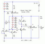
You mentioned using a Zener, that one should be oriented in reverse regarding its cathode vs the LEDS shown in the above. Also a Zener will take much more uF value in C1 for effective filtering (higher than 6.8V Zeners, especially when at below 7.5mA operating current are noisy, and they keep on climbing for noise with the less mA is used to bias them).
You mentioned using a Zener, that one should be oriented in reverse regarding its cathode vs the LEDS shown in the above. Also a Zener will take much more uF value in C1 for effective filtering (higher than 6.8V Zeners, especially when at below 7.5mA operating current are noisy, and they keep on climbing for noise with the less mA is used to bias them).
Sorry was 18v not 15
18V Tx for 15V DCout is ok too. It will allow for some more dissipation from the first MOSFET than a 15V Tx but it will make it respond faster too. MOSFETS like higher voltage across them up to 25V VDS or so. From there on they get no better for their pF. When the constant current setting (CC) in the reg for an application is below 500mA the dissipation does not get out of hand fast. As you progress to higher settings for CC and Vout you would want to be conservative with the transformer voltage not to result in much more than 5V DCin-DCout. Because heat builds up faster on the sinks with every excessive Volt now. Power is current times voltage nobody escapes that law.
18V Tx for 15V DCout is ok too. It will allow for some more dissipation from the first MOSFET than a 15V Tx but it will make it respond faster too. MOSFETS like higher voltage across them up to 25V VDS or so. From there on they get no better for their pF. When the constant current setting (CC) in the reg for an application is below 500mA the dissipation does not get out of hand fast. As you progress to higher settings for CC and Vout you would want to be conservative with the transformer voltage not to result in much more than 5V DCin-DCout. Because heat builds up faster on the sinks with every excessive Volt now. Power is current times voltage nobody escapes that law.
so do you recommend to have 5V above the target regulated voltage for lets consider +/-12VDC after regulation? I agree the point of much heater and I dont think in general we will have such a huge voltage drop from mains for such lower voltage. Consider even 10% is just 2.4V of voltage drop if its 24V.
How good is the ccs by itself? I have circuits that need filtering but not regulation and am thinkin of using the ccs part of this circuit
anybody?

im trying to weight this versus dn2540+lm317 ccs
anybody?
im trying to weight this versus dn2540+lm317 ccs
Jack's 1.1 vs 1.3 PSRR test using a vector network analyzer:
https://www.diyaudio.com/forums/pow...-ultrabib-shunt-regulator-35.html#post5501267
I tried the DN+LM thing once as tube's CCS plate load in my 6V6 preamp and I don't know what I did wrong but I could hear much noise.
Hi Nick,
Simple, any noise in that circuit is heading out of the output terminal. The only worse place might be in the cathode circuit where there would be more gain. I strongly doubt you would use a current source in a grid circuit unless bypassed with a very low impedance.
-Chris
Simple, any noise in that circuit is heading out of the output terminal. The only worse place might be in the cathode circuit where there would be more gain. I strongly doubt you would use a current source in a grid circuit unless bypassed with a very low impedance.
-Chris
Yes its the output node but that CCS was supposed to be of minimal self noise. Anyways, its an old experiment that I just remember the outcome, but something must had rubbed the tube in the wrong way vs simply a 5k plate resistor. It produced a marked rise in hiss with no buzz or bias instability to suggest oscillation. The bias current with plate load CCS was set the same as before when it was all resistors.
- Status
- This old topic is closed. If you want to reopen this topic, contact a moderator using the "Report Post" button.
- Home
- Amplifiers
- Power Supplies
- The simplistic Salas low voltage shunt regulator