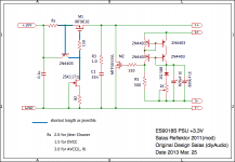
Reflektor +3.3V
Hi, Reflektor lovers.
For last three months, I have tried to optimize the Reflektor, and found some useful knowledge.
1) M2
I guess that lesser the Cxxx of M2, better becomes the sound.
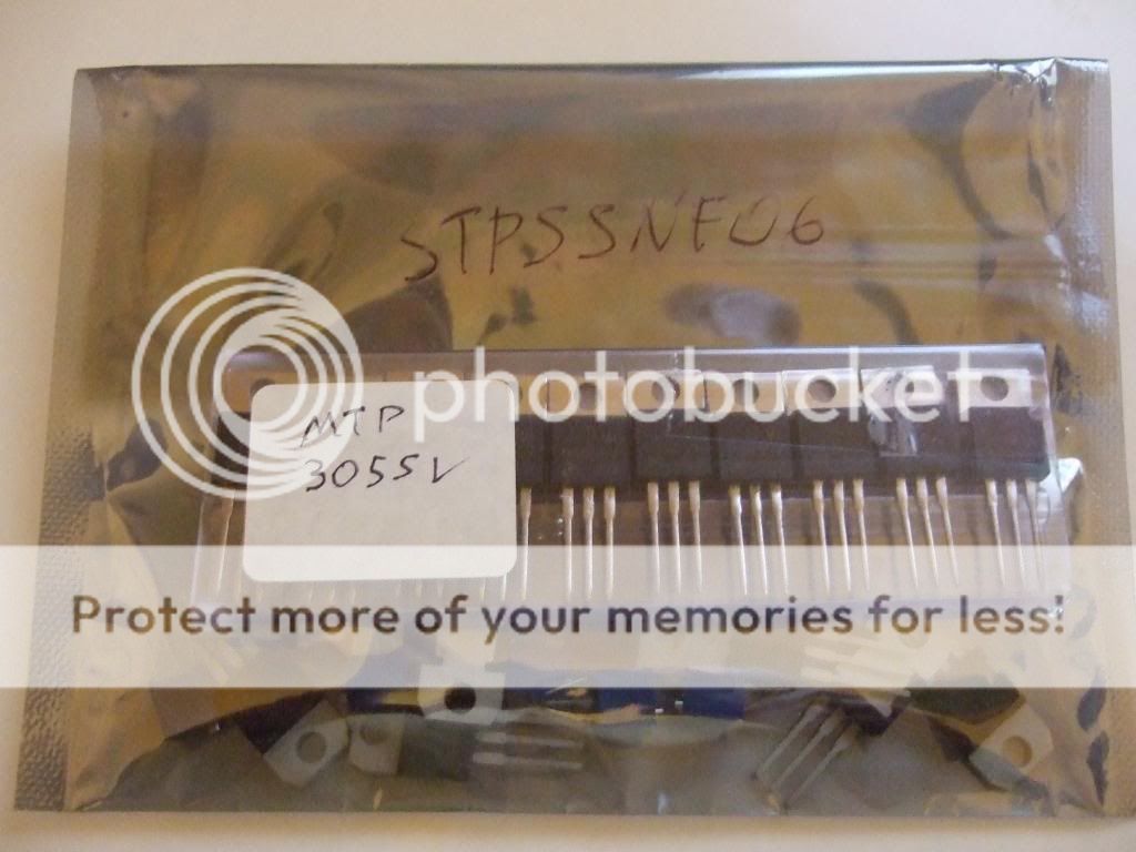
For this reason I replaced STP55NF06L with MTP3055VL.
2) R5
R5 acts important factor. This determines the current of Wilson Current Mirror. And M2 is driven by this. After some tests, 500R is preferred.
I realized 500R by paralleling two 1K VARs.
3) Zobel
As for C1, we must take into account two factors, that is, value and quality. When either factor was missed, I didn't satisfy.
As a result of a lot of testing, I adopt 33nF capacitor made of mica.
Outcome is very remarkable.
IMO there is no peak, no valley no noise but is open, smooth, and clear field.
I am noticed that my previous Reflektor had some weak points comparing to new one.
There is only real music playing soulful. I am satisfied very much.
It may be strange, I feel the volume has become larger than before, approximately 3dB or more.
Again I would like to say that Reflektor is excellent.")
Hi, Reflektor lovers.
For last three months, I have tried to optimize the Reflektor, and found some useful knowledge.
1) M2
I guess that lesser the Cxxx of M2, better becomes the sound.
For this reason I replaced STP55NF06L with MTP3055VL.
2) R5
R5 acts important factor. This determines the current of Wilson Current Mirror. And M2 is driven by this. After some tests, 500R is preferred.
I realized 500R by paralleling two 1K VARs.
3) Zobel
As for C1, we must take into account two factors, that is, value and quality. When either factor was missed, I didn't satisfy.
As a result of a lot of testing, I adopt 33nF capacitor made of mica.
Outcome is very remarkable.
IMO there is no peak, no valley no noise but is open, smooth, and clear field.
I am noticed that my previous Reflektor had some weak points comparing to new one.
There is only real music playing soulful. I am satisfied very much.
It may be strange, I feel the volume has become larger than before, approximately 3dB or more.
Again I would like to say that Reflektor is excellent.
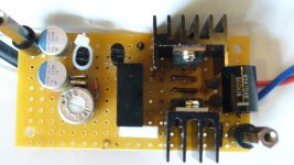
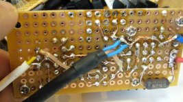
Attachments
Hi Kazuo-san,
Thanks for sharing this. I've noticed you got 2 820uf Nichicon LE polymer caps on Vref. Have you tried others? (Polymer caps usually have high leakage current which result in more noise on Vref) For the zobel, I got good result with C0G/NP0 ceramic, but I like your idea of silver mica. I guess HF is important for digital power here.
Thanks for sharing this. I've noticed you got 2 820uf Nichicon LE polymer caps on Vref. Have you tried others? (Polymer caps usually have high leakage current which result in more noise on Vref) For the zobel, I got good result with C0G/NP0 ceramic, but I like your idea of silver mica. I guess HF is important for digital power here.
Intersting stuff Kazuo! Thank you for sharing!
I replaced the potentiometer / led (or diode) combination in the reference leg by a voltage reference diode from the LM4040 range. I did this in order to make the reference leg as low-ohmic as possible. In that way the Reflektor will give the largest possible reaction in the regulation leg, and doesn’t only rely on capacitor impedance. The disadvantage is that you can not trim the output voltage exactly (unless you add a small pot or resistor anyway), but have to search for the best combination of available reference diodes, taking into account that the two transistors add 1.2V to the output voltage. In this case for 3.3V output voltage you would need a 2.1V reference diode, or a single green LED could do the job to start with. I bypassed this with 2x 1000uF/25V Nichicon Muse KZ capacitors, which are the best I have tried so far. I have bypassed these Nichicons with foil capacitors with small resistors in series, like a zobel circuit (resistors are a few Ohms or less). Experiment with different resistor values. This gives the opportunity to voice it and get the best sonic results. I use multiple bypasses ranging from bigger to small. The results are amazing.
For the zobel across the shunt, I measure with an oscilloscope the output for stability. As long as that there are no oscillations I lower the capacitor value to as small as possible. My application remained stable with no zobel at all. So I don’t have a zobel here. But I don’t use the original CCS, because of stability issues I ran into. Others seem to have no problems, but I switched to a different CCS design.
Peter
Peter there are many CCS to have like depletion cascode from SSHV2 or the LEDS one from 1.1 etc. but your problems could just be needing a faster PNP control BJT in the simple Reflektor CCS plus some input decoupling? Or you use some active pre regulation that interacted?
Hi Kazuo-san,
Thanks for sharing this. I've noticed you got 2 820uf Nichicon LE polymer caps on Vref. Have you tried others? (Polymer caps usually have high leakage current which result in more noise on Vref) For the zobel, I got good result with C0G/NP0 ceramic, but I like your idea of silver mica. I guess HF is important for digital power here.
Thank for your sincerely advice.
In fact I am using BG caps on +5.0V Reflektor. But I did not test difference of changing caps.
It may be worth to try your idea.
Thanks
Intersting stuff Kazuo! Thank you for sharing!
I replaced the potentiometer / led (or diode) combination in the reference leg by a voltage reference diode from the LM4040 range. I did this in order to make the reference leg as low-ohmic as possible. In that way the Reflektor will give the largest possible reaction in the regulation leg, and doesn’t only rely on capacitor impedance. The disadvantage is that you can not trim the output voltage exactly (unless you add a small pot or resistor anyway), but have to search for the best combination of available reference diodes, taking into account that the two transistors add 1.2V to the output voltage. In this case for 3.3V output voltage you would need a 2.1V reference diode, or a single green LED could do the job to start with. I bypassed this with 2x 1000uF/25V Nichicon Muse KZ capacitors, which are the best I have tried so far. I have bypassed these Nichicons with foil capacitors with small resistors in series, like a zobel circuit (resistors are a few Ohms or less). Experiment with different resistor values. This gives the opportunity to voice it and get the best sonic results. I use multiple bypasses ranging from bigger to small. The results are amazing.
For the zobel across the shunt, I measure with an oscilloscope the output for stability. As long as that there are no oscillations I lower the capacitor value to as small as possible. My application remained stable with no zobel at all. So I don’t have a zobel here. But I don’t use the original CCS, because of stability issues I ran into. Others seem to have no problems, but I switched to a different CCS design.
Peter
Thank for your sincerely advice.
I am very glad you have same idea of mine.
Actually I have already realized this idea on 5.1V Reflektor using with two Red LEDs, and 3.9V Reflektor using with one Red Led and one diode.
I am attracted your idea of vref zobel, you bother me
Thanks
Some notes.
1) M2. Higher gfs Mosfets in higher output voltage Reflektors will have less disadvantage for Cxxx than under 5V operation. The various capacitance phenomena lessen with more voltage. So for users of higher Vout they should compare again the two types mentioned. Higher gfs will lower Zo.
2) R5. Using lower threshold Mosfets lowers the mirror's current with same 1K as it was for normal threshold Mosfets. So 500R looks in the right direction in your build. But other users with higher voltage outputs and normal VgsTh Mosfets should try again and compare.
*About snubber across Vref capacitor it was there in the original posting describing the Reflektor idea. R.C. had played with that back then also. Then dropped as too tweaky, but happy to know such an approach provided for the patient builder in the end.
**About active fixed ref good parts let me remind IR LEDS and LM329 6.9V precision reference low noise also for higher outputs.
Many adequate parts we can't afford not to check in different situations must be in our parts bins.
Thank you for your contribution Kazuo
If I did not your previous reports posted on #4451 or 4453, I would not have come up with the idea to try various value of C1.
I thank your effort.
 Don't tell everywhere, but yes, it is.
Reflektor R5 (1k) listening tests
After reading Kazuo’s remark about the influence of R5 (1k) in post #5801 I decided to run some listeningtests myself.
First a little explanation regarding R5. R5 determines two important values:
1. The current in the Wilson current mirror. Ic = Vgs/R5. The higher the R5, the lower the current in the current mirror.
2. The amount of correction signal fed to M2 to counteract output voltage change. The higher R5, the higher the amount of correction signal. Were this circuit a DAC, then R5 was the IV resistor. Actually it is an IV resistor, because current change in the current mirror is converted to voltage here to drive M2.
The question is, what is a greater sonic advantage: a higher current in Wilson current mirror or a stronger correction signal?
Listening tests:
I started with R5=1k and paralleled it with another 1k, just like Kazuo did. In comparison with 500 Ohm music sounded a bit more rounded and friendly than with 1k, but also less dynamic and airy, and with 1k there was more micro detail. So I decided to look what happens if you increase (instead of decrease) R5. Because this boosts the correction signal it is important to check the output for stability with an oscilloscope. I went from 1k to 2k, to 3.3k, to 4.7k, to 7.5k and ended with 13k. I listened to every single step back and forth and with every step there was an increase in spaciousness and detail, without any additional harshness. 7.5k was very detailed, full and warm. 13k was clearly the best but was a fraction more lightweight than 7.5k. The disadvantage is that with 13k the Ic of the current mirror has dropped to 0.3 mA (in my case with IRF840 and Vgs = 3.98V). In all cases the output remained stable. So no issues here.
Also the kind of resistor had quite an influence on how it sounded. For example a Vishay CMF55 resistor sounded in comparison to an old non-magnetic carbon film a bit cold and technical, and I preferred the character of the carbon film.
Peter
- Status
- This old topic is closed. If you want to reopen this topic, contact a moderator using the "Report Post" button.
- Home
- Amplifiers
- Power Supplies
- The simplistic Salas low voltage shunt regulator