A trimmer of 200 ohms or even 500 ohms is fine. I would set it to about 70 ohms to start, which should allow about 300mA idle current through the shunt mosfet. First use a passive load, a 100 ohm high power resistor, that would draw about 120mA, so the mosfet passes about 180mA now. If everything works, then increase the trimmer to about 170 ohms, or whatever you want, while measuring the current through the shunt. To make it easier to measure the current, you can use 0R1 for R1, and measure the voltage drop across it, then 100mV across R1 would be 1A current. The Idss of J2 in the simulation is between 7 and 8mA. It is not so important, since you can adjust the trimmer.
For J3 and J4 you can also use anything between 7 and 10mA. Better towards 7mA. The Idss of J1 does not really matter, between 7 and 11mA is fine.
If it oscillates, you can try a 100nF cap on C-B pins of Q1. If it still oscillates, then most likely it's a problem with the choice of Q1 and Q2.
Ask any other questions if stuck.
@ikoflexer
Are you sure to use BFT92 transistor? SMD part with small breakdown voltage?
And why 2N2222, where is difference between BC550 & 2N2222?
Bandwith? (300 Mhz for BC550, >250 Mhz for 2N2222)
Capacitance? (<4 pF for BC550, <8 pf for 2N2222)?
Only area where ancient 2N2222 is better, is max.power dissipation?
Could anyone recommend a broadband PNP that's not SMD and with higher Vceo? The bft92 has a Vceo of 15V which is a bit tight for the 12V application here, but should work. I know it's a pain that it's surface mount, so, please recommend something else, anyone.
As for the 2N2222A vs the BC550, as I didn't build this I have only the simulation to go by. With the BC550 (a few different models) the regulator is not stable. With all the 2N2222A models the simulation is stable. Normally I build a circuit before I recommend a configuration, but in this case, I can't do it right now because I'm busy with something else. If Tham can wait I will build it myself and then can make recommendations based on real experiences, not simulations.
As for the 2N2222A vs the BC550, as I didn't build this I have only the simulation to go by. With the BC550 (a few different models) the regulator is not stable. With all the 2N2222A models the simulation is stable. Normally I build a circuit before I recommend a configuration, but in this case, I can't do it right now because I'm busy with something else. If Tham can wait I will build it myself and then can make recommendations based on real experiences, not simulations.
@ikoflexer
which shematic is correct for v2, post #823 or #857 ?
Just my curiosity, why RF transistor which work into Ghz range?
With low voltage there is limited use of this great shunt regulator.
For DACs & other low voltage applications is OK, but 40V or 50V versions like v1?
which shematic is correct for v2, post #823 or #857 ?
Just my curiosity, why RF transistor which work into Ghz range?
With low voltage there is limited use of this great shunt regulator.
For DACs & other low voltage applications is OK, but 40V or 50V versions like v1?
stormsonic said:@ikoflexer
which shematic is correct for v2, post #823 or #857 ?
Just my curiosity, why RF transistor which work into Ghz range?
With low voltage there is limited use of this great shunt regulator.
For DACs & other low voltage applications is OK, but 40V or 50V versions like v1?
Hi stormsonic,
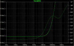
Here's how I see the situation. IMHO v1 is an excellent regulator from many points of view. I've said it before, I'll say it again: low parts count, easy to assemble, stable and robust to small parts variations. Very good psrr and output impedance. Have a look at the output impedance plot I attached, which is for v1. Look at the shapes. The dotted line is the phase angle. Note how Zout is pretty flat up to about 10kHz. The phase shift starts increasing pretty rapidly after 1kHz. There are some people who think that a flat curve to higher frequencies for both Zout and for the phase would be beneficial. See jbau's thread on the lm317/lm337 regulators
http://www.diyaudio.com/forums/showthread.php?s=&threadid=143539&perpage=25&pagenumber=10
for some arguments for this. v2 was the result of my trying to both lower and flatten the output impedance and its phase angle at least in the audio frequency. As soon as you want high loop gain at higher frequencies you get in trouble because it is highly likely that the circuit will become unstable and oscillate badly. So you see, we left the nice world of v1, where it's actually hard to make it oscillate, and enter the world of v2 and v1.5, where it is hard to make it NOT oscillate, while still maintain a small parts count, and have great performance (psrr and zout). Greater loop gain and wideband, sounds like RF, right? Hence the use of RF transistors in that position. It does not have to be the bft92, that's just one part that I happen to find while searching in a hurry for an RF transistor. There are many to use, but the higher the frequency of operation, the lower the chance of phase shift, and therefore of oscillation. Please correct me if I'm wrong; I'm just a beginner.
Another great thing about v1 is that you can make it work for low current, high current, low voltage, higher voltage, with almost no changes to the topology, and with just a few resistors changed here and there. Unfortunately, v2 and v1.5 are not as universal. That's why, for a specific application, it seems I have to change it quite a bit to make it work well and stable. I'd say that v2 can work well for lower current type applications (< 200mA load) where you want very low output impedance with a flat shape well into the 100 to 200kHz range. I was thinking specifically that DACs may benefit from this. Tham used v2 even for some other circuit and he reports an improvement, perhaps because of the flat phase in the audio range.
Post 857 is the latest version of v1.5 and that's the one to try for flat Zout to higher frequencies, 12V output, and high current. I specifically put this together for Tham's request to power his t-amp, and I think I'll use something like this for my chipamp when I get some time to do it.
Sorry about so many changes, and any confusion this may bring, but really, we're exploring right now. With the time this will stabilize and as more people implement and give feedback, we'll improve it and have some sort of final recommendation. There are many regulators to choose from, and if you want something true and tried, v2 and v1.5 is not it yet. Welcome to the bleeding edge
")
Attachments
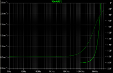
For comparison, so you see what I'm talking about, here's the output impedance plot for v1.5. Please do not read too much into it. This is just a simulation. In reality both v1 and v1.5 will behave quite differently, depending on layout and many other real world factors. We're just comparing designs here, until someone with proper measuring equipment can actually measure them and report the findings.
P.S. This simulation for v1.5 used mpsh81 as Q2, and mpsa18 as Q1, with 5R base resistor, and 5pF cap on B-C pins.
P.S. This simulation for v1.5 used mpsh81 as Q2, and mpsa18 as Q1, with 5R base resistor, and 5pF cap on B-C pins.
Attachments
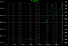
Salas said:How will V1 fair for early HF phase turn if you substitute IRF9510s in the sim?
Improvement. But now it needs compensation at high freq, because as it is it oscillates. Probably a small cap on B-C pins of the NPN driver would do.
Attachments
Standard stuff. You make it lighter for Ciss, it opens, but it gets more dangerous and ups impedance. Nahh, I prefer it conservative as it is V1. Better go V2 for more open, so we do it in the drive department.
I wonder if it is the phase turn or the better drive that gives an audible edge to V2. We can bump on reacting circuits up high though, like closed loop small phone amps or little class A amps. Depends on synergy.
I wonder if it is the phase turn or the better drive that gives an audible edge to V2. We can bump on reacting circuits up high though, like closed loop small phone amps or little class A amps. Depends on synergy.
Hi Salas, ikoflexer,
Good looking project you have on the burner here. Howdy from a neighbor.
Hi stormsonic,
Will they work? Probably.
Will they reliably work? Don't know, but not from what I have seen and I'm not a betting man.
The proper way to reduce the range of a control is to use fixed resistors. You probably want to set a minimum resistance, so one fixed is needed right there. Then you just figure out what adjustment range you want and split that between the fixed resistances and the total resistance of the final fixed resistor. If someone wants a different adjustment range, they only need to change the fixed resistors. No biggie and the home constructor can exercise their noodle some.
-Chris
Good looking project you have on the burner here. Howdy from a neighbor.
Hi stormsonic,
I'd say that a multi-turn trimmer is the last thing you want in there. Remember that both the contact area and pressure are lower than a standard trimmer. If you are going to pass any current through it at all, it's important to stay away from multi-turn types.For trimmer I will recommend multiturn type. With ordinary trimmer it is difficult to set shunt current.
Will they work? Probably.
Will they reliably work? Don't know, but not from what I have seen and I'm not a betting man.
The proper way to reduce the range of a control is to use fixed resistors. You probably want to set a minimum resistance, so one fixed is needed right there. Then you just figure out what adjustment range you want and split that between the fixed resistances and the total resistance of the final fixed resistor. If someone wants a different adjustment range, they only need to change the fixed resistors. No biggie and the home constructor can exercise their noodle some.
-Chris
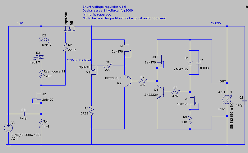
anatech, it will pass only few mA, depends on Idss od JFET bellow trimmer. Edit: J2 on Iko's shematic above.
For example, let's say 6 mA.
VLED=1.85V (for 3 mm red LEDs, I am using)
Trimmer value formula: (Vbias-VLED1-VLED2) / Idss = (4.5V-1.85V-1.85V) / 0.006 A = 133 Ohm
You will need 133 Ohm resistor, to set Vgs to 4.5V.
Looking at datasheet for IRFP9240, if you have Vgs at 4.5V and Vds is 5V, then you are shunting approx. 1.5A
6 mA accross 133 Ohm will result into 0.798 voltage drop on resistor. With 0.798 V and 0.006 A you will dissipate 0.0048W on trimmer
If you want to shunt less, then you should reduce Vgs, let's say to 4V. (4V-1.85V-1.85V) / 0.006 A = 50 Ohm
6 mA accross 50 Ohm will result into 0.3 voltage drop on resistor. With 0.3 V and 0.006 A you will dissipate 0.0018W on trimmer
But I agree with you, with fixed resistor you will eliminate possible problems.
the maximum current that a trimmer track can pass is determined by the maximum power the whole track can dissipate.
A 400mW 1k pot can pass sqrt(p/r) = sqrt(0.4/1000) = 0.02A = 20mA.
This is the maximum.
I recommend that you never pass more current than would exceed 50% dissipation.
This reduces the usable current to <=14mA for a 1k 400mW pot and <=20mA for a 500r 400mW pot.
A 400mW 1k pot can pass sqrt(p/r) = sqrt(0.4/1000) = 0.02A = 20mA.
This is the maximum.
I recommend that you never pass more current than would exceed 50% dissipation.
This reduces the usable current to <=14mA for a 1k 400mW pot and <=20mA for a 500r 400mW pot.
Resistor function in V1
There have been a number of different renditions of the V1 regulator. Some of these have a resistor between the zener and Q3 (the BC550), but some do not. What is the function of this resistor? Is it to drop the voltage from a reference that is too high?
Thanks for the explanation!
There have been a number of different renditions of the V1 regulator. Some of these have a resistor between the zener and Q3 (the BC550), but some do not. What is the function of this resistor? Is it to drop the voltage from a reference that is too high?
Thanks for the explanation!
It is a base stopper resistor to improve on oscillation guard. Its a bit better transiently without, but in some layouts a good measure.
Another thing you may saw is having two resistors on the left if with a vbe (transistor) controlled ccs or one and a jfet.
It is effectively one resistor split in two for creating a middle point so to bootstrap the CCS transistor with a capacitor. This is a Douglas Self trick. Now in some of Ikoflexer's iterations, one jfet local ccs is simulating a much bigger resistor in place of one of the pair but keeps the current adequate for a bit better performance still. If short on jfets, the two resistors are OK enough though.
- Status
- This old topic is closed. If you want to reopen this topic, contact a moderator using the "Report Post" button.
- Home
- Amplifiers
- Power Supplies
- The simplistic Salas low voltage shunt regulator