50V will work but use higher, they get less noisy if not stressed in the reverse time. 4 times is a good rule of thumb if you plan getting parts. I prefer R-Core, EI, toroid, in that order. Keep EI and toroid away from the PCBs and any signal cabling. EI has its less field perpendicularly to its narrow sides. Toroid has its most to the direction of secondary exits, R-Core gives practically zero hum field issues.
an X rated cap will not explode when connected across the mains.
Didn't say x rated caps.
Taking a 10uf cap, pretty good chance.
X rated for common mode L,N
Y common mode >gnd. L,N,G
Thanks. So for 12VAC 70V at least, so MUR105 (50V) isn't enough. Would it be better to use PCB transformers or toroid?
Why use noisy MUR's. Try Schottky's 30V-50V whatever you can find.
no, 50v is the 3xrms limit for a bridge reverse rating on a 12vac secondary, that is why i recommended 4x for no stress. Don't go under 50v on this questioned example. If preferring schottky 50v ok then. Murs are good, fast, low leakage switching grade parts btw.
31dq05
I could use 9VAC also, so 50V would be just enough.. What Schottkys then?")
Don't know, I don't use so low regs, my lowest was for DCB1S. CRT La Ode who has drawn the boards was liking 1N5819. Will do OK with 9VAC. Is it for a DAC BTW?
thank you..... need to use big caps across mains.... acoustica.org.uk: shocking!
then ****.Didn't say x rated caps.
Don't ever suggest anything except X and Y rated caps for mains use.
 No personal remarks gentlemen.
Bill,... So I am going to redo my preamp level raw supply before the CCS-shunt regulator to change it from CLRC to LRC and see if I can find any subjective improvements.
... The only thing I am not sure is this: there may be a significant amount of DC which may saturate the inductor core making the inductor ineffective. I don't know if this can be a case so am seeking experts' advice on this.
Is your preamp sensitive to CM noise? Each shunt should eat AF ripple and superfluous input impedance (*) but I don't know to what extend the combined shunts are rejecting CM noise (**).
Modifying a CD player a couple of years ago I learned noise can soften up reproduction. From making tube amps I learned much of the subjective quality depends on excluding noise. Unnatural sound might hint at this phenomenon.
In tube building it's good practice to oversize current tolerance, take three times the measured current to be on the safe side with your chokes. For low capacitance there are multi section RF chokes.
Bill,
Is your preamp sensitive to CM noise? Each shunt should eat AF ripple and superfluous input impedance (*) but I don't know to what extend the combined shunts are rejecting CM noise (**).
Modifying a CD player a couple of years ago I learned noise can soften up reproduction. From making tube amps I learned much of the subjective quality depends on excluding noise. Unnatural sound might hint at this phenomenon.
In tube building it's good practice to oversize current tolerance, take three times the measured current to be on the safe side with your chokes. For low capacitance there are multi section RF chokes.
I am not sure yet, but I am very excited to hear my newly upgraded power amps perhaps late today and see if I can still hear any tiny bit of grains in my system at all.
Things are a bit hectic now and I am getting too busy with all sorts of things happening at the same time. I lost my job two weeks ago so I thought I should have a plenty of time to do my HiFi stuff but in reality I am more busy than ever! So things are progressing slower than I expected.
Anyway, I have just applied the "the small choke input" hypothesis I posted a couple of pages back to my 6 monoblocks. I replaced all the rectifier diodes to Fairchild Steath, removed the snubbing caps, added the 220uH input chokes, padded with 0.1R resistors, relocated the first caps so that I could fit in the 2nd and 3rd caps up closer to the circuit, with a long copper bar to shield the AC wires, added aluminium sheet shield around the AC socket and built a second aluminium wall to completely shield the circuit boards from the power supply section, redid the aluminium bus, redid the grounding and wiring, etc. Now the PSUs are all done. If I have luck today I will hear them later today.
I did some measurements half an hour ago. I was so excited to see that the rails are CLEAN, CLEAN and CLEAN! Before the upgrades, I saw quite a bit of high frequency junk on the rails. Now the scope shows thin saw-tooths that are text-book like.
As for the Fairchild Steath, the scope still showed a bit of high frequency switching noise at 1mHz to 3mHz with magnitude up to 5mV immediately after the diodes and before the chokes, but comparing to the previous garden variety bridge, is much, much cleaner. I am happy to see that the small chokes and the large caps completely get rid of all of the high frequency noise, and I spent half an hour could not find any of it.
I can't wait to hear my system with the "NEW" amps, although they have a theoretical 115dB PSSR across the entire audio bandwidth so in theory the upgrade to the PSU should make no difference.
I would like to get my power amps "perfect" first before I work on my CCS-shunt regulators so that I can get a good subjective evaluation of various caps and arrangements.
I could use 9VAC also, so 50V would be just enough.. What Schottkys then?
Four 31dq05 Schottky diodes for your fwbr.
VDS for 2Sk170
Dear Salas,
seems that your regulator works fine for many people, so this question might be superflous, but it has been nagging my mind for a while:
The 2Sk170 JFET, J1, in the attached schematic has only about 0.7 V (Ube of Q2) as Vds. Will J1 then really operate as it should, ie as a CCS, as J1 is in its linear range instead of in its saturated range?
Should Vds not be several Volts for J1 to work as a CCS?
Regards,
Attachments
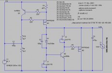
That question has been replied before in this thread. But obscure to find anymore. 2SK170 has small -Vto (pinch off). -0.4 to -0.5V for BL. Lower for GR. With 0.7V positive Vbe to nest in, it gets over 1V VDS, more than double pinch off, not only to work, but to work steady, since it satisfies the double pinch off rule of thumb. It has low self noise as a part too, and enough IDSS to grab a Zener or some LEDs. Higher pinch off parts would demand a voltage lift of the error amp's emitter and AC decoupling for that, not to degenerate it and lose much loop gain. More parts and audible caps, less potential for working near to Vgs as in shunts for DACS.
Dear Salas,
with its 188 pages it is not easy to find
Yes, the 2Sk170 is indeed one of the best JFETs around, and still easy to source.
Thanks for the reply!
Regards,
with its 188 pages it is not easy to find
Yes, the 2Sk170 is indeed one of the best JFETs around, and still easy to source.
Thanks for the reply!
Regards,
That question has been replied before in this thread. But obscure to find anymore. 2SK170 has small -Vto (pinch off). -0.4 to -0.5V for BL. Lower for GR. With 0.7V positive Vbe to nest in, it gets over 1V VDS, more than double pinch off, not only to work, but to work steady, since it satisfies the double pinch off rule of thumb. It has low self noise as a part too, and enough IDSS to grab a Zener or some LEDs. Higher pinch off parts would demand a voltage lift of the error amp's emitter and AC decoupling for that, not to degenerate it and lose much loop gain. More parts and audible caps, less potential for working near to Vgs as in shunts for DACS.
Don't know, I don't use so low regs, my lowest was for DCB1S. CRT La Ode who has drawn the boards was liking 1N5819. Will do OK with 9VAC. Is it for a DAC BTW?
Yep, that DAC End I mentioned..
Should I use metal film or wirewound resistors in R1, R7 & R13?
Last edited:
Metal film 0.5-1W will do nicely. That 2W spec is too much for what you want it, not that it will do any harm either, its for when running it with other values and much more current. Must have been transfered from the spec of the 200mA sets with circa 10R resistors.
Thanks.. Is there any real difference between 27R & 33R? Digikey has 5pcs minimum in those, so I think I will use only one value.
27R runs about 75mA when 33R runs about 60mA. I did not set those for that DAC. I would only think there is more drawn on the one with the 27R and they wanted to keep the proportions between supplied and shunted current about the same in all 3 parts. More will not hurt, just check that the sinks don't feel too hot.
- Status
- This old topic is closed. If you want to reopen this topic, contact a moderator using the "Report Post" button.
- Home
- Amplifiers
- Power Supplies
- The simplistic Salas low voltage shunt regulator