So capacitors are unavoidable in this circuit and worst of all... they leave a signature.
That is why I am so interested in finding the best and available, most suitable for each position. (Maybe a combination of Nichicon + Rubycon ?)
I must thank Bill for the precious input regarding several caps effects... I will keep experimenting and reporting the news.
I do not know what a "perfect system" might be but maybe one without caps and no TX in the signal path.
I dream of using resistors without any impedance or inductance.
Meanwhile I rely on everybody´s input to colate as much info as possible so I can use my mind and hears to decide.
It is a complex and time consuming process but gives really good results.
Before each mod I ask loads of questions and read all the available info. Based on previous experiments I start building a "probable resulting image" that helps me decide the next action.
Sometimes my mods produce unexpected results (like replacing a silver stranded wire by a copper coax - improves definition by lowering induced noise also cutting high freq forwardness) but the majority of the times all the mods produce exactly what I was waiting for.
Regards
Ricardo
Guys, there's something that I haven't measured, which is using LED's instead of the zener, without a bypass cap. If you guys test that please let us know what results you get. I forget in which thread I came across a function to add the noise of each LED when using several in series. Something like sqrt of the sum of each led noise squared... but I don't remember exactly. In any case, the noise is additive. The question to be answered is, how many LEDs will it take to make the noise comparable to a zener?
The addition of noise in a led series is sublinear. I.e. Not so bad, but then again more. Gotta know the particular Zener and the number of leds so to compare. Up to 10-15V, leds are a manageable number and mostly preferable between 6-10V where Zeners are bad due to their physics.
Ok, I started to begin a V1 build yesterday but then realised I had a couple of different schematics & options. I was missing some parts such as BC550C & BC560C. I also realised that I don't understand the operation of the circuit & couldn't make informed decisions on substitutes for these parts.
I'm initially looking to build a high current (up to 3A) 12V & 19V version then I wanted to try a V2 version for 5V DAC powering.
So, at the risk of repeating information that has already been posted here, could somebody give a brief description of the operation of the circuit, the options for low current & high current usage, the options for low voltage & higher voltage operation?
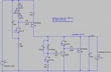
I started with Iko's schematic attached but realised I hadn't any BC550C or BC560C but had BC546C & BC556C which might substitute? I then saw another version that used LEDs instead of upper BC560C but don't know how much voltage these should drop or if they can handle the high current I need. Salas posted that approx 3k or 2k2 could be used in place of the zener for the voltages I needed.
Generally, I ended up chasing my tail - I need help to get a handle on this
I'm initially looking to build a high current (up to 3A) 12V & 19V version then I wanted to try a V2 version for 5V DAC powering.
So, at the risk of repeating information that has already been posted here, could somebody give a brief description of the operation of the circuit, the options for low current & high current usage, the options for low voltage & higher voltage operation?
I started with Iko's schematic attached but realised I hadn't any BC550C or BC560C but had BC546C & BC556C which might substitute? I then saw another version that used LEDs instead of upper BC560C but don't know how much voltage these should drop or if they can handle the high current I need. Salas posted that approx 3k or 2k2 could be used in place of the zener for the voltages I needed.
Generally, I ended up chasing my tail - I need help to get a handle on this
Attachments
Have a look at post 1191, that's the version with LEDs.
You can change the output voltage to what you want with a different zener. You can expect the voltage to be the zener voltage + 0.6 approximately.
For the LED version you only need one npn, the bc550c. If you have access to mpsa18, that works well too. bc546c should work, but if not ideal.
To set the CCS current make R1 small. The actual value will depend on the voltage drop across the LEDs. I usually start with a small current and small load to rule out any mistakes in the circuit. Then increase the current in a few steps. You could start with a 200R resistor as load, and 10R as R1. Then make R1 smaller until you get the current you want. Do not underestimate the need for heat sinks. At 2-3A you need to dissipate serious heat.
HTH
Thanks Iko,
I have some 12V zeners. This voltage rating is reported as being low noise, I think? So I could do the 12V shunt with this. Is the top CCS a BC560C or LEDs? In the BC560C version, what are the two 4.7K R4 & R10 in series for? In the top CCS LED version are the LEDs expected to drop the input voltage down to slightly above the expected o/p voltage?
I don't have many 5W for R1 to try out, just 0.68 & some 0.47 2W
I have some MPSA14s, will these do as replacements for the BC550C?
I believe my heatsinks are probably the only thing that I have which is adequate for the job!
Last edited:
Remember you can always optimize it later for low noise and all that. If the zener is bypassed by a 1000uF cap you're left with very little noise; it takes some effort to beat that.
R4 and R10 are part of the CCS biasing. C1 further lowers the psrr; it's a trick which Walt Jung has used at some point, and I'm sure many others.
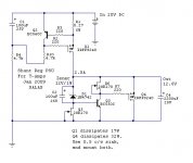
The main element of the CCS is the mosfet. The LEDs are used to drop the voltage so that there is a particular and ideally fixed voltage difference between the gate and source of the mosfet. But you see that it's hard to control the value of this voltage difference only with LEDs, because you can add or remove one LED, which takes away or adds about 1.8V, or 2V, depending on the type of LED. So the LEDs are for a rough choice of Vgs voltage, and then the finer setting is done with R1.
How about anything in the 6 to 15 ohms? No matter the wattage. You can build a prototype with that, small current. It'll allow you to measure the circuit, to get acquainted with it. A high current version can go up in smoke so easily, with any little mistake. I have proof
Not really, mpsa14 is a darlington, huge hfe. You're better off with the bc546c if you have nothing else on hand and you want to get a prototype working.
R4 and R10 are part of the CCS biasing. C1 further lowers the psrr; it's a trick which Walt Jung has used at some point, and I'm sure many others.
In the top CCS LED version are the LEDs expected to drop the input voltage down to slightly above the expected o/p voltage?
The main element of the CCS is the mosfet. The LEDs are used to drop the voltage so that there is a particular and ideally fixed voltage difference between the gate and source of the mosfet. But you see that it's hard to control the value of this voltage difference only with LEDs, because you can add or remove one LED, which takes away or adds about 1.8V, or 2V, depending on the type of LED. So the LEDs are for a rough choice of Vgs voltage, and then the finer setting is done with R1.
I don't have many 5W for R1 to try out, just 0.68 & some 0.47 2W
How about anything in the 6 to 15 ohms? No matter the wattage. You can build a prototype with that, small current. It'll allow you to measure the circuit, to get acquainted with it. A high current version can go up in smoke so easily, with any little mistake. I have proof
I have some MPSA14s, will these do as replacements for the BC550C?
Not really, mpsa14 is a darlington, huge hfe. You're better off with the bc546c if you have nothing else on hand and you want to get a prototype working.
Ok Iko,
I can use 6 to 15 ohm in R1 along with 3 LEDs for a low current version to start with - I'm confused again, though, as in your schematic for the Tripath (below) you show 15 ohm for R1 but this would be a high current version?
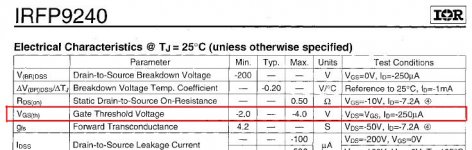
What VGS value are we aiming for across the IRFP9240? Does this vary depending on what voltage/current we want or is it not just a threshold value above which the Mosfet works?
Given that I get a prototype working how do I calculate what value 5W R1 I need to order to get the current I want - let's say 2.5A?
Sorry for all the Qs
I can use 6 to 15 ohm in R1 along with 3 LEDs for a low current version to start with - I'm confused again, though, as in your schematic for the Tripath (below) you show 15 ohm for R1 but this would be a high current version?
What VGS value are we aiming for across the IRFP9240? Does this vary depending on what voltage/current we want or is it not just a threshold value above which the Mosfet works?
Given that I get a prototype working how do I calculate what value 5W R1 I need to order to get the current I want - let's say 2.5A?
Sorry for all the Qs
Attachments
Last edited:
About 1R 5W, most likely a little less given the tolerances. Post 1219 says how and is only one page back!!! And has been said so many times before! These are hands on circuits, dead simple. Put one together, start doing simple measurements on a dummy load. If stable, connect the amp.
P.S.
Vgs is batch and V&I related, not given. I have seen between 3-4V in such regs.
P.S.
Vgs is batch and V&I related, not given. I have seen between 3-4V in such regs.
Attachments
I did some digging around in my parts box & found some BC550C which I can use in the bottom CCS
I also found some BC559 (but not C grade) - can these be used in top CCS? I fancy going this route instead of LEDs & 2SK170BLs as I don't have many of these & I can't get them as easily as I can get BC560C
Edit: OK, Salas, I know this must be annoying to you, answering Qs a number of times - I haven't been able to read through all the pages (I know the anser to my Q was just one page back, so no excuse really)
Last edited:
@jkeny
My best advice to you would be to put together a prototype. It's simple enough to do an air sculpture, or even a fancier point to point if you really want. My prototypes are all air sculptures. First I mount the power mosfets to a heat sink (large) Then I use two solid copper wires about 1.5mm thick, one for ground, and one for main V+. All the other parts get soldered somewhere in between. At times I might use some short wires to reach from one part to another.
Then, measure and measure again. You will learn a lot that way. Change some resistor, and measure again.
Excellent work! Congratulations!
Thank!
you can sent for me your Adress, an E-mail??
My E-mail : **************
Quanghao
- Status
- This old topic is closed. If you want to reopen this topic, contact a moderator using the "Report Post" button.
- Home
- Amplifiers
- Power Supplies
- The simplistic Salas low voltage shunt regulator