W.Jung has his own web site.
He has dozens of articles in there.
Yes, Walt I know
") .
.Whitlock immediately made me think of Simon Whitlock, the Wizzard from Down Under.
After you connect the Source, then the 10k has no effect on noise, it is paralleled with the Source output impedance, ~10r to 1k0
Okay. Then it helps with... discharging the input caps... a little faster
. 1M, no problem !Attachments

Don't just change it because I said so. Read up on why balanced impedance works and why certain values are chosen to get the best from the connection.
Then adopt what seems a good value.
That brings me back to that original question. I saw 10k and wondered, "why did he choose that value?" so I asked hoping to hear some different explanation.
Then adopt what seems a good value.
That brings me back to that original question. I saw 10k and wondered, "why did he choose that value?" so I asked hoping to hear some different explanation.
I've seen 10k used in another design and thus adapted it. In my mind it serves no other purpose as to help discharging the input cap, and omitting it would yield the highest possible input impedance. On the other hand I'm not sure I need a defined input impedance at all, since the output impedance of the DUT will always be pretty low.
Yes the key is mode conversion based on unbalanced impedances. The great benefit of a well-balanced measurement is the rejection at the differential receiver of conducted and radiated disturbances, especially from magnetic fields which are difficult to shield against.
The technique of bootstrapping has been around for a long time. I haven't looked at Bill's patents, but I suspect they are more to do with the schemes developed for his Ingenius chip to protect against overloading and destruction from accidents involving 48V phantom power.
But I'm happy for him. I never thought I'd see the day when he endorsed active circuits as being better than transformers Of course if you need galvanic isolation, forget it.
The technique of bootstrapping has been around for a long time. I haven't looked at Bill's patents, but I suspect they are more to do with the schemes developed for his Ingenius chip to protect against overloading and destruction from accidents involving 48V phantom power.
But I'm happy for him. I never thought I'd see the day when he endorsed active circuits as being better than transformers
Of course if you need galvanic isolation, forget it.Hmmm, I don't get any difference in CMRR, neither by varying the input resistors nor by adding the bootstrap circuit. The theory behind all this bootstrapping stuff is over my head, so if the sim doesn't work this isn't for me .
Anybody willing to give the sim a try and find what I'm missing?
.Anybody willing to give the sim a try and find what I'm missing?
Attachments
Okay, did another try after some days of non-audio related thinking.
Whitlock writes in his articles that the bootstrap is there to increase the common mode input impedance. This works incredibly well in the sim, peaking at about 1.2G, which is rather unrealistic, but nonetheless it's considerably more than 22k. Everything else being equal and only the input impedance being higher for CM, there can't be any difference in CMRR if the source impedance is low with 10R. Thus I increased the source impedance of the CM voltage source to 1meg. Now I get a 1% monte-carlo-worst-case-CMRR of more than 140dB, but, without the bootstrap and 22k only, it's even better with 180dB!
What's going on here? What is the source impedance of radiated common mode noise? Seems like I still haven't found out how to use spice properly for this case...
It may be conducted CM owing to the computer's safety ground referencing and switchmode power supplies. If your loop areas are small you are at least minimizing B field effects.
You are correct though --- a <10 ohm source Z should be an easy load for avoiding mode conversion. And you can also experiment by padding out the "ground" return. But I suspect it will have little effect.
Short of a spectrum analyzer, I find a portable AM/FM radio is helpful in locating interference sources.
I get a long way toward meaningful measurements using a little purpose-built a.c.-coupled JFET gain-of-~30 preamp located right at the site of the device under test. Battery powered, with a big cap across the batteries. Crude, and primitive compared to Gerhard, but I'm not trying to be metrologically exquisite. I could parallel a few more SK170 if need be. It's also easy to put a cap across the output drain resistor, remembering that for noise a first-order lowpass has a noise bandwidth of pi/2 of the -3dBr bandwidth.
Hi ,
I build a TPA3116 amplifier (19v) that gives a theoretical draw of 45w at 8ohm..about 2Amp
Of course in real life (music) its about 1/8a = 0.35a . Actual measurement its 0.31A
Can I use one of those salas regulators based on above numbers ? Should I use a capacitor bank after the regulator to help with the peaks ?
Will it increase the clarity of sound ? Has anyone used it on class D amplifier ?
Even if terribly inefficient, yes they had used itHi ,
I build a TPA3116 amplifier (19v) that gives a theoretical draw of 45w at 8ohm..about 2Amp
Of course in real life (music) its about 1/8a = 0.35a . Actual measurement its 0.31A
Can I use one of those salas regulators based on above numbers ? Should I use a capacitor bank after the regulator to help with the peaks ?
Will it increase the clarity of sound ? Has anyone used it on class D amplifier ?


You should not add any extra capacitor. No point. Then you will listen to the slower capacitor

Click those links to read about both your questions
http://www.diyaudio.com/forums/powe...tize-general-shunt-reg-pcb-2.html#post1995942
http://www.diyaudio.com/forums/powe...tize-general-shunt-reg-pcb-3.html#post2015919
Hi Salas ,
ok understood for the above.
I have a second scenario:
DAC with headphone amplifier (TPA5122 needs 3.3v and headphone about 5v)
In this case whats the best way to go. I understand that having 2 separate shunt regulators will be best but it adds too much to BOM
Can I use a shunt regulator for the 5v (split rails) and feed 5V to headphone amp and on second rail use a LDO and feed 3.3v to DAC IC ?
I read that LDO after shunt regulator does not offer any benefits..but this seems the best compromise.
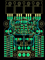
Just finished refining my small 5x5cm layout and ordered a couple of boards from China.
The new measurement preamp will have to wait some time though, since my house is making progress and I'll be busy doing the electrics anytime soon now...
The new measurement preamp will have to wait some time though, since my house is making progress and I'll be busy doing the electrics anytime soon now...
Attachments
Hi Salas,
I am testing a BIB board to power a DAC, setup to output 9v ~500ma. The regulator board will be in a separate enclosure so i plan to run two wires between them, and just jumper the sense wires locally on the PCB. Question is, how will regulator board react if the dac cable is suddenly disconnected and there is no load, will it handle this scenario ok or will that cause issues?
Cheers,
Mark
- Status
- This old topic is closed. If you want to reopen this topic, contact a moderator using the "Report Post" button.
- Home
- Amplifiers
- Power Supplies
- The simplistic Salas low voltage shunt regulator