Its not a version of V1. Its HV next of kin. Has a variable ring of two Iccs that creates a variable Vref on a resistor. Uses no output capacitor. Just a Zobel terminal. Everybody who tried it had it working but they got it only as high as 120mA at 200-400V. It was meant for phono and line stages. Why it really gave you such a hard time is still a mystery to me. The higher current asked? Some kickback from the test trafo and filter?
Kofi Annan, and sonata149 did the latest ones I know of. Sonata's report.
Kofi Annan, and sonata149 did the latest ones I know of. Sonata's report.
which transistor/s failed first?ikoflexer said:my parts cemetery was my experience. ........................
......... how to protect the parts at high voltage and possibly against high inrush current?
Here is the high voltage thread where I gave more details. It's been a while since I've attempted the HV regulator and I tried many things then.
It was probably some mistake I kept doing then, it's still a mystery why it failed. Perhaps this thread isn't the right place for a HV discussion, sorry.
It was probably some mistake I kept doing then, it's still a mystery why it failed. Perhaps this thread isn't the right place for a HV discussion, sorry.
Hi AndrewT
Okay let's do it... (refer to schematic of post#554 for component names)
J2 becomes a resistor, but since it's connected between the base and the emitter of transistor Q3, nothing much exciting will happen. The minute current increase/decrease will not change the voltage drop accross DZ, since this is a Zener (constant voltage vs current characteristic).
J3 provides a bias current to Q3, which results in Q3 having a certain transconductance gm (=40*Ic).
Now lets replace it with a resistor as you suggested. Say we take 1/gm for our J3.
Now there is a sudden 10mV increase on the input of the sense structure (node "RemoteSense")
What happens next with the voltage at the gate of the PMOS M3...

AndrewT said:Hi, do that mind game, replace the two CCSs with resistors.
Okay let's do it... (refer to schematic of post#554 for component names)
J2 becomes a resistor, but since it's connected between the base and the emitter of transistor Q3, nothing much exciting will happen. The minute current increase/decrease will not change the voltage drop accross DZ, since this is a Zener (constant voltage vs current characteristic).
J3 provides a bias current to Q3, which results in Q3 having a certain transconductance gm (=40*Ic).
Now lets replace it with a resistor as you suggested. Say we take 1/gm for our J3.
Now there is a sudden 10mV increase on the input of the sense structure (node "RemoteSense")
What happens next with the voltage at the gate of the PMOS M3...
Hi Ikoflexer,
with your latest incarnations of the shuntreg you put a lot of emphasis on the ultra low output impedance of the circuit. The overall goal of the regulator is to provide the cleanest possible supply to the load circuit. Salas's regulator uses 2 means to this end; the series current source at the input and the shunt regulator at the output. In view of the inevitable resistances in wires, PCB track, component leads etc, I'm wondering if reducing the shunt impedance further brings any added value. With output impedance at the micro-ohm level, would it not be time to turn your attention to improving the PSRR of the input current source and spend a few components there.
maybe cascoding of Q1 will bring you more "bang-for-the-buck", without venturing into conditional stable territory. It seems you've no objection against spending some more trannies
Hi Ikoflexer,
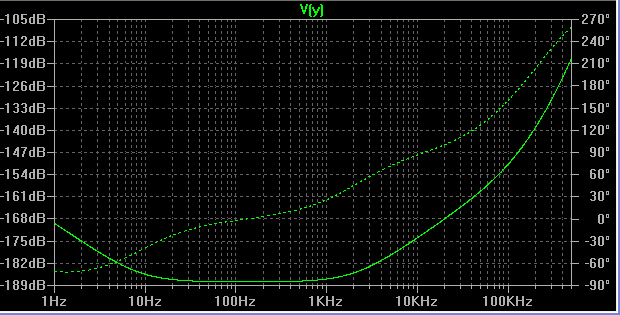
Indeed this is an impressive PSSR you achieve.
How much of this 190dB is due to the input current source and how much is due to the sub 0.1mOhm shunt impedance?
If you stick a 1 Ohm resistor between the drain of M2 (the input series PMOS) and the shunt, what is the PSRR at the drain of M2? The intention would be to limit the shunt impedance to 1 Ohm, to test a more 'real life' situation with cables and all.
In practice it would probably be easier to achieve a high current source output impedance then a super low shunt impedance...
Anyway with these super numbers you achieve we're deep in the 'learning for fun'/academic debate realm. It's great that you also build these circuits and try them out!
Maybe I should buy a couple of those IRF's and join the fun
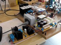
This photo is a long due promise to salas.
It's a +-16V Salas shunt powering an OPA627 line stage. It replaced a battery supply with glory. It is powered continuously for one and a half month now without any problem. It keeps astounding me with it's sound that's why I don't bother to rework the wiring and close the box..As salas mentioned at the beginning of this thread I have used 2Ns and still haven't find the time to replace them with 2Sks. Who knows perhaps it will get better sonically...
It's a +-16V Salas shunt powering an OPA627 line stage. It replaced a battery supply with glory. It is powered continuously for one and a half month now without any problem. It keeps astounding me with it's sound that's why I don't bother to rework the wiring and close the box..As salas mentioned at the beginning of this thread I have used 2Ns and still haven't find the time to replace them with 2Sks. Who knows perhaps it will get better sonically...
jeepee said:Hi Ikoflexer,
Indeed this is an impressive PSSR you achieve.
How much of this 190dB is due to the input current source and how much is due to the sub 0.1mOhm shunt impedance?
If you stick a 1 Ohm resistor between the drain of M2 (the input series PMOS) and the shunt, what is the PSRR at the drain of M2? The intention would be to limit the shunt impedance to 1 Ohm, to test a more 'real life' situation with cables and all.
In practice it would probably be easier to achieve a high current source output impedance then a super low shunt impedance...
I'm not saying it's not possible, but the things I tried didn't work. You can easily play with the circuit using the free ltspice simulator. I can provide you with all the models and whatever needed. Very easy to use. The offer is valid for anyone who would like to do it.
Anyway with these super numbers you achieve we're deep in the 'learning for fun'/academic debate realm. It's great that you also build these circuits and try them out!
We are, I agree. I don't think it's wrong, as long as we try to also make it real.
Maybe I should buy a couple of those IRF's and join the fun
Clean and cheap fun, what can I say. If this is the kind of fun that you appreciate, what are you waiting for?

jameshillj said:Iko,
On the above cct, those zeners 4756 (47volt) and 4757 (51volt) will kill the poor ol' k170s pretty quick!
I see you're looking for 200 volt at about 700 mA (140VA?) - have to go towards that "ring of ---" cct for the high volt version, methinks.
Hi James, the voltage drop across them shouldn't be large when the operating points are reached, but maybe for short times this would happen, I'll have to look into it. Thanks!
AndrewT said:M2, the CCS pass element, provides the inrush protection.
It is designed to limit the maximum current into the circuit to it's set value.
Check the dissipation on this device at switch on, i.e. maximum voltage at the input and zero voltage on the +ve rail.
The 9240 should be able to survive an ampere with a 50V input for the very few seconds it takes to charge up all the capacitors that follow the CCS.
Check the dissipation in M1 and M4. They will have different Vds but the same Id.
R1 should allow you to check Id.
Is there a possibility that oscillation is causing the failure rather than over current?
Gate voltage protection Zeners? Where are they? Vgs < Vgs max ALWAYS even during start up, shorting out, shut down, etc.
Andrew, yes, it may have oscillated. The thing is that it happened usually very fast. I'd hear a pop and done. I should try it again soon, and I'll open a new thread, then I'll give you a shout if you can help a bit it'd be great.
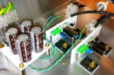
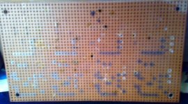
Marinos said:Oops the photo
Very nice! You have also used this white board for your high voltage shunt. What material is it? You just drill as many holes you need? Does not look perforated.
- Status
- This old topic is closed. If you want to reopen this topic, contact a moderator using the "Report Post" button.
- Home
- Amplifiers
- Power Supplies
- The simplistic Salas low voltage shunt regulator