

Looks good, fast work! Good luck when trying it!
I envy your ability to make a PCB so quickly and neatly! Assuming it works and gives good results I think the next step would be to try and arrange the MOSFETs on the PCB for easier heatsinking. Probably hard to get them all along one edge but mabye mounted flat underneath the board with holes to fix bolts through? Straight onto a moderately thick aluminium casing
I envy your ability to make a PCB so quickly and neatly! Assuming it works and gives good results I think the next step would be to try and arrange the MOSFETs on the PCB for easier heatsinking. Probably hard to get them all along one edge but mabye mounted flat underneath the board with holes to fix bolts through? Straight onto a moderately thick aluminium casing
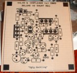
Just a quick update; the pcb is populated and it hasn't caught on fire on initial power on. There are some issues with proper biasing so it needs to get debugged. We'll get back with updates when we got more.
And yes, good point, the heat sink situation is not ideal right now, it'll have to be redone.
And yes, good point, the heat sink situation is not ideal right now, it'll have to be redone.
Some thoughts about the pcb.
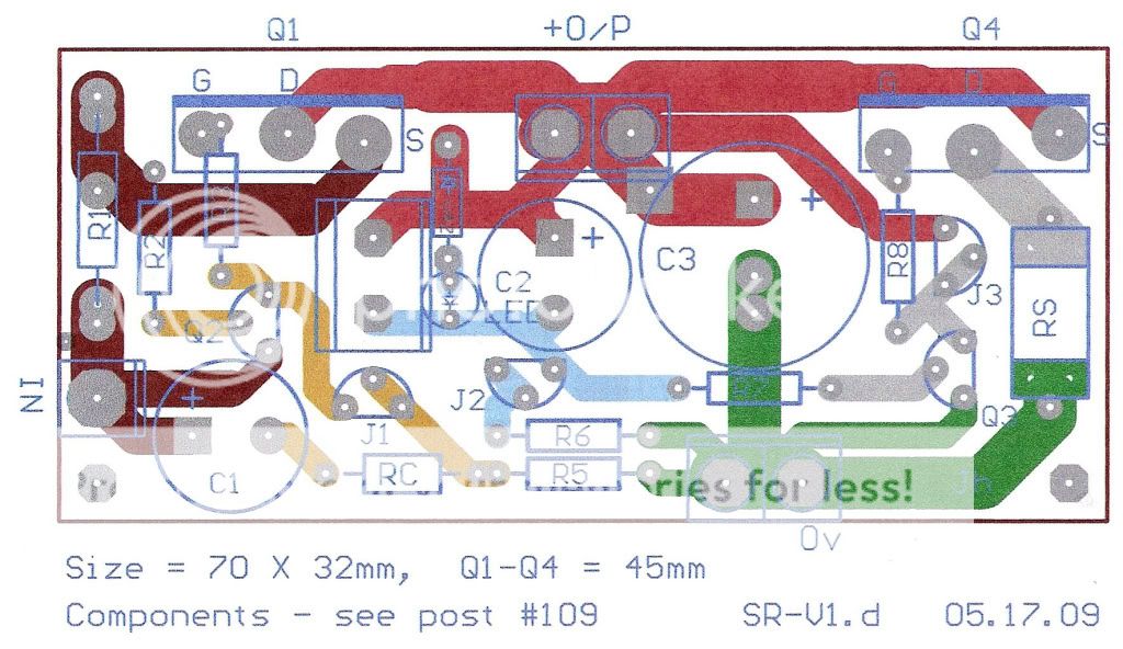
First, it's a concept design with the colours to highlight the 4 different areas of the cct. The star track approach is to show the seperate current paths, some of which can be combined together later.
Transistors are now around the right way and the parts are fairly tight, but only a few require change after assembly.
The R1 has donuts for // R's, and the zener has an extra space for a series led - however, the un-named rectangle next to these is aWeidmuller socket/plug for easy replacement of the zeners.
The big IRFP's (Q1, Q4) can be mounted both on the top component side or underneath - from below, the legs are bent up and will stand-off the pcb about 10mm (see corner donuts for spacers).
If mounted vertically, there isn't easy access to the +O/P terminal, but can just use a single connector like the IN one, or turn it sideways, or use the "Han" connector pins, or the pins from Neutrik connectors (with h/shrink jackets)
The RC (R capacitor) is easily changed - same for RS (shunt), (options of a SMD or // R's) or just linked.
The j1 can be replaced with R4, vertical.
The C3 is the O/P cap and is now a 15mm dia (for 470u/50v Silmics, etc) or for a vertical axial cap that can easily have added series R on + leg, if required.
I remember that Jan Didden emphasized the trouble that low ESR caps can produce on the O/P of most regulators, but I like the sound of the Silmics and the Sikorels, both low ESR, and neither seem to produce any problems in this cct - but it's something to keep in mind for other designs.
Comments?
There are many ways of doing pcbs - it would be good to see some other designs - Ikoflexors for the V2 prototype is a rather different design - let's see some more.
thanh1973 said:Hi Salas
Have you tried this regulator on the B1?
If so is there audible differences than just using just a switch mode power supply?
I am guessing the B1 is already good since there is little attenuation of the signal because of the zero gain design.
Don't know, never made any with shunts.
As for guessing, yes it has good SNR, but on the other hand OPA627s have good PSRR and Marinos could clearly listen better with shunts in his line pre...
James, well done! The pcb looks good indeed.
After some initial hickups I got V2 to work, the schematic has slightly changed and I will post it in the near future. Unfortunately my headphone amp is still suffering from a "slipped probe" accident so I cannot comment on the sound. More tests are needed to see how it compares to v1 or other solutions in reality, but for now, it is functional.
After some initial hickups I got V2 to work, the schematic has slightly changed and I will post it in the near future. Unfortunately my headphone amp is still suffering from a "slipped probe" accident so I cannot comment on the sound. More tests are needed to see how it compares to v1 or other solutions in reality, but for now, it is functional.
Hi Dr.EM, I'm refining the post #209 layout and adding some space around the components that'll be most often replaced/changed. When I did an actual size "print and fit" mockup, it was very cramped for a general purpose design - and as it's pretty small (70 x 34 mm) a few more mm will make a big difference.
The tracks seem too thin, altho they're 1.75mm wide and the donuts need to be a bit bigger for multiple changes.
Hoping to have most of the bugs sorted out by the end of the week - any suggestions are most welcome - just write them here, or PM to me.
The negative board is the same except for turning the k170 back to front (and reversing the caps, zeners, etc) and there is a dual TO-92 arrangement for this, so it's just the one pcb for both rails. (and maybe a dual rail single board, too)
The IRF9610's will fit (same pins) - it's a cheaper device, but not as good.
is it the devices that are not as good?jameshillj said:The IRF9610's will fit ............................ but not as good.
or
is it that the models used by the sim are not as optimistic?
- Status
- This old topic is closed. If you want to reopen this topic, contact a moderator using the "Report Post" button.
- Home
- Amplifiers
- Power Supplies
- The simplistic Salas low voltage shunt regulator