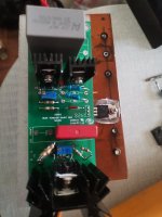
Hey Salas, I am late to the party but can I purchase pcb SSHV2 somewhere? I have used your designs before and am delighted with the results.
Be safe, John.
Hi
Its included in a Group Buy from time to time or pm the organizer in case he currently has any extra
gb-salas-sshv2-regulator
Updates not to search in a long thread
Hi,
with the new DIY forum version the shortcut to SSHV2 is now broken… it point at something else..
could somebody fix it please?
thank you
Hmmm. The link to the troubleshooting posts seems to be taking me to the top of this "last" page in this thread, not to the first post in the section. Also, when I got my first email with the new forum, I was taken to the first page of the thread, not the last. I was, not surprisingly, logged out due to the move, but I still expected it to take me to the new posts or to request that I log in. Not sure this is a bug a but I thought I'd report it here because you, Salas, are the man...
Now it takes me to the troubleshooting post. But I see the rest of post#1 links shoot to end of thread too and I am looking for the original posts now to try link again.
Better report in the forum problems section. Because I am not admin to fix a bug if its because of the new platform transfer.
Better report in the forum problems section. Because I am not admin to fix a bug if its because of the new platform transfer.
Yes, seems suitable. It could also possibly play the role of the top cascoding Mosfet offering higher Vgs across a faster bottom one of lower own Vgs allowing it to reach higher mA closer to its IDSS. The DN2540N8-G has minimum 150mA IDSS spec for instance if allowed to.
In any case it takes to experiment with either two of those IXYS in the cascode or a different types combination as mentioned to determine max CCS current and suitable source resistance value for the application's load+spare current goal.
In any case it takes to experiment with either two of those IXYS in the cascode or a different types combination as mentioned to determine max CCS current and suitable source resistance value for the application's load+spare current goal.
I mean for the sshv2
https://www.diyaudio.com/community/...et-hv-shunt-regs.134801/page-104#post-2805889
https://www.diyaudio.com/community/...et-hv-shunt-regs.134801/page-104#post-2805889
- Home
- Amplifiers
- Power Supplies
- Simplistic MosFET HV Shunt Regs
