Hi Salas. I would like to ask you since the power supply box is separate from the preamplifier, I read that the two outputs must be short-circuited to transform it into a classic feed, there are contraindications if I reach the outlet directly with 4 twisted wires and then I start with a plug with 2 wires?
Hi Salas,
Im using your schematic to build a regulator for 90vdc and 80mA. The 3281 pnp trans I replaced with mje350 and the 1k//vr 5k , other one is same. How ever, Im getting stuck. I can’t change the output voltage (130vdc) with the dc electric load (I built it base on Dave on eevblog) at 80mA. Also conect S0 F0 s+ f+
I took some measurements: V 1.8k = 0
Vec of pnp = 0, the other one is 3.5-5.x V
Can you please help me out, I’m just electric hobby not pro
Which one schematic of all? Verify the voltage reference resistor(s) are not too high value for 90V. Verify the constant current you set is higher than the load mA.
I’m using the hv2 schematic
You mean the two 68k? Can I change to 27k?
For the load, I couldn’t change the value more than 0.7V (70mA)
I will try to change 68k, hope it works
Thank you so much!
Even if you made no other mistake and the key JFET is genuine, do lower the 68K resistors when looking for 90V output range anyway. Try whatever logically smaller values you have in hand first.
In post#1 there is a link on how to test the CCS section (DN2540s) in low voltage safe mode. The constant current you set must cover for the load mA and then some. That dialogue continuing until the troubleshooting member had solved an issue in the shunt voltage section. Good hints there.
In post#1 there is a link on how to test the CCS section (DN2540s) in low voltage safe mode. The constant current you set must cover for the load mA and then some. That dialogue continuing until the troubleshooting member had solved an issue in the shunt voltage section. Good hints there.
Even if you made no other mistake and the key JFET is genuine, do lower the 68K resistors when looking for 90V output range anyway. Try whatever logically smaller values you have in hand first.
In post#1 there is a link on how to test the CCS section (DN2540s) in low voltage safe mode. The constant current you set must cover for the load mA and then some. That dialogue continuing until the troubleshooting member had solved an issue in the shunt voltage section. Good hints there.
Thank so much for guiding me. I followed your method then I found the Zenner and Jfet are defected.
I changed 68k to 27k
Now it works but still have minor issue because I replaced k117 with j112. Will be fine when I get k117
")
I thought that it was because of the jfet.
The mje350 I changed to B1357
Irf630
Here is my picture
5E5A2EC3 52A8 4E71 9845 BF0E919D9B2D - Up ảnh nhanh khong cần tai khoản
The mje350 I changed to B1357
Irf630
Here is my picture
5E5A2EC3 52A8 4E71 9845 BF0E919D9B2D - Up ảnh nhanh khong cần tai khoản
It is most probably due to the improper JFET. As it gets hotter it gives more current to the I/V converting ref resistors. The more improper type it is the more it does. Blow air on its spot with your mouth and if the output suddenly drifts much, its certainly about the JFET.
K117GR does it less while remaining low noise type. It has smaller VGS (OFF) and more GOS than the J112. Not really indifferent to thermal changes but better behaving in this circuit. If you can insulate the JFET from ambient temperature somehow, a mini housing over it maybe, it helps. But find a K117 if you can and then you decide if original spec drift is already satisfactory for your application.
K117GR does it less while remaining low noise type. It has smaller VGS (OFF) and more GOS than the J112. Not really indifferent to thermal changes but better behaving in this circuit. If you can insulate the JFET from ambient temperature somehow, a mini housing over it maybe, it helps. But find a K117 if you can and then you decide if original spec drift is already satisfactory for your application.
Not included, you must add it as spare. So its 15+20=35mA to set.
Thanks Salas
Not included, you must add it as spare. So its 15+20=35mA to set.
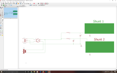
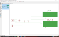
Here are two simulations for the raw dc, I will use a rectifier tube, not wanting to stress the tube too much, I would prefer to put 100uf after the L, but that peak voltage for the first seconds worries me a little, what do you think Salas? Could it be harmful to the shunt? The second simulation is with 190uF and the peak has disappeared, could that capacity be enough to shunt? Adding a second filter cell with CRC for the two channels, it seems to me wasted given the use of the shunt or could it help filtering? Two shunts will be used one per channel.
Attachments
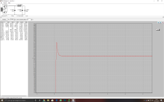
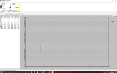
Avoid a peak. For various reasons, not only possible harm. Glitches can activate the choke to radiate an interference field. 220uF standard value for C2 should be enough for your moderate mA. 100Hz ripple the reg it does not mind it much, its EMI/RFI can leap in. Striding over fences via stray inductance in cables and layout. But the choke should help enough in that. Depends on how high a frequency it remains significantly inductive. Real C2 will not have 2Ω ESR across its useful bandwidth though, smaller.
- Home
- Amplifiers
- Power Supplies
- Simplistic MosFET HV Shunt Regs