anything that might benefit from a CCS shunt regulator,Salas said:What are you going to power with it
i.e. every electronic circuit that is not a power amp.
What's against stable, low impedance power with low noise and great bandwith for an amps' PS?AndrewT said:anything that might benefit from a CCS shunt regulator,
i.e. every electronic circuit that is not a power amp.
Do you perhaps hint at the use of active anode loads making the pro's of a shunt superfluous?
Thinking about an all electrical supply for a new power amp I soon abandoned the idea as the driver
tube needed a higher anode voltage than the output tubes.
I gave up on the idea of a series type regulator in front of the shunt, because dissipation becomes
substantial for a 20+20W tube amp.
It might do miracles on small power amps though, like the Darling which operates at a single HT voltage.
Hi,
a power amp can be made to work in conjunction with a regulator, if one's design expertise is up to the task.
But a shunt regulator, surely, can't be a candidate for a power amp's supply?
I would think if one is going down this route one would select a series regulator topology.
Maybe I'm wrong.
a power amp can be made to work in conjunction with a regulator, if one's design expertise is up to the task.
But a shunt regulator, surely, can't be a candidate for a power amp's supply?
I would think if one is going down this route one would select a series regulator topology.
Maybe I'm wrong.
That's another cup of teaAndrewT said:Hi,
try doing that on a power amp with shunt regulator.
How much power do you plan to use to swamp the power amp consumption?
")
In case of a shunted power supply one has to know exactly the maximal current draw. That depends not only on the steady state condition but also on the clipping state on loud passages. The latter best be under 80% of the total current set in the shunt. It is largely depending on topology and measures to prevent clipping (feedback?) but should be determined by experiment and measurement.
The higher the bias and the bigger the sinks or constant tube dissipation of the audio unit the better the customer for a shunt it is. Small class A like JLH69 and 96 for the low voltage version or small SE amps for the HV version are in for a nice reg and amp package. If the juice is already burned then the shunt only has to top it for headroom. Keeps the shunt constant waste at minimum.
If it has loop feedback it will to the most I presume.
In general, stiff supply sounds less powerful if the amp can not satisfy the speakers is paired with. Sag tends to breath with and its a form of soft compression. The key is to take measurements and know what are the real peak demands on certain speakers and listening habits so to efficiently set the reg without burning too much just to have spare or less than really needed.
In general, stiff supply sounds less powerful if the amp can not satisfy the speakers is paired with. Sag tends to breath with and its a form of soft compression. The key is to take measurements and know what are the real peak demands on certain speakers and listening habits so to efficiently set the reg without burning too much just to have spare or less than really needed.
wild idea
Not being very gifted with solid state I ventilated this [OT] idea some time ago to Gary Pimm.
It's more appropriate to larger amps than to sputs but it might be worth the effort.
In order to optimize a shunt regulators' efficiency it should be able to change its set current when
power consumption is demanding such. A kind of servo action. Would it be possible to sense the
ampliers' current draw ahead of the actual amplification and adjust the CCS as needed?
The biggest bottleneck might be the slowness of the current rise.
A very simplistic (hey, where did I hear this before ) solution would be a 10 to 20% increase
depending on the rotation of the volume control.
Not being very gifted with solid state I ventilated this [OT] idea some time ago to Gary Pimm.
It's more appropriate to larger amps than to sputs but it might be worth the effort.
In order to optimize a shunt regulators' efficiency it should be able to change its set current when
power consumption is demanding such. A kind of servo action. Would it be possible to sense the
ampliers' current draw ahead of the actual amplification and adjust the CCS as needed?
The biggest bottleneck might be the slowness of the current rise.
A very simplistic (hey, where did I hear this before
) solution would be a 10 to 20% increase depending on the rotation of the volume control.
Re: wild idea
I've been thinking about this for some time, but I'd be reluctant to use something more automatic. If anything, I'd do first a simple and reliable system (attenuator?) that would choose between several pre-set resistors, with a nice analog display of idle shunt current, and regulated voltage.
I have no problem with a nice power amp powered with a shunt regulated. If I was into efficiency I'd be all over class-d stuff. But that's just me.
disco said:Not being very gifted with solid state I ventilated this [OT] idea some time ago to Gary Pimm.
It's more appropriate to larger amps than to sputs but it might be worth the effort.
In order to optimize a shunt regulators' efficiency it should be able to change its set current when
power consumption is demanding such. A kind of servo action. Would it be possible to sense the
ampliers' current draw ahead of the actual amplification and adjust the CCS as needed?
The biggest bottleneck might be the slowness of the current rise.
A very simplistic (hey, where did I hear this before
depending on the rotation of the volume control.
I've been thinking about this for some time, but I'd be reluctant to use something more automatic. If anything, I'd do first a simple and reliable system (attenuator?) that would choose between several pre-set resistors, with a nice analog display of idle shunt current, and regulated voltage.
I have no problem with a nice power amp powered with a shunt regulated. If I was into efficiency I'd be all over class-d stuff. But that's just me.
Re: wild idea
Krell's plateau bias could be translated in plateau shunt ICCS. Just another wild idea.
disco said:Not being very gifted with solid state I ventilated this [OT] idea some time ago to Gary Pimm.
It's more appropriate to larger amps than to sputs but it might be worth the effort.
In order to optimize a shunt regulators' efficiency it should be able to change its set current when
power consumption is demanding such. A kind of servo action. Would it be possible to sense the
ampliers' current draw ahead of the actual amplification and adjust the CCS as needed?
The biggest bottleneck might be the slowness of the current rise.
A very simplistic (hey, where did I hear this before
depending on the rotation of the volume control.
Krell's plateau bias could be translated in plateau shunt ICCS. Just another wild idea.
Nothing wrong with brainstorming. The crux of the Krell idea seems to be the stepped increase/decrease of the bias current for a fixed time according to some algorithm based on how dynamic the signal is. The steps are discrete, sort of like shifting one gear up/down at a time. Not sure of the details.
I don't think that an automatic change of the shunt current would work, UNLESS there is another shunt before the shunt Only that way the current suddenly demanded by the original shunt could be given timely enough.
However, something that does not react to the music might work, and instead, react to a low limit of the the actual shunt current. Monitor the shunt current, and as soon as it is below a certain threshold, increased it by a predetermined amount, for a number of fixed times.
I don't think that an automatic change of the shunt current would work, UNLESS there is another shunt before the shunt
Only that way the current suddenly demanded by the original shunt could be given timely enough.However, something that does not react to the music might work, and instead, react to a low limit of the the actual shunt current. Monitor the shunt current, and as soon as it is below a certain threshold, increased it by a predetermined amount, for a number of fixed times.
AndrewT said:
But a shunt regulator, surely, can't be a candidate for a power amp's supply?
I would think if one is going down this route one would select a series regulator topology.
Maybe I'm wrong.
From a technical standpoint, I think it can be done. The obvious disadvantage is the power dissipation. But there are people who would still get a Veyron, even though you get 9 miles per gallon (city), which is about
30 liters of gas every 100kms. Would a power amp sound better with a shunt regulator? Let's find out.
Hi Salas! thank you you help me!
I want to ask him about the principles of operation of this circuit shunt regulator ???
You can show me the parameters to be measured by the R out of the shunt regulator??? Noise and Humm
I need one circuit for the pre with voltage: output 260v / 80ma one channel, and can adjust the voltage out! With vi in 300V to 350V!
You can give me one cricuit for my pre!
Thank
You can see the cricuit ! how The value and C- R-C befor shunt regulator???
Attachments
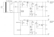
All the principles have been discussed in the thread. If you have read the thread and you still don't see how to scale it, clamp it, start it, calculate the voltage drop on its CRC pre filter etc. then, I am sorry I don't give targeted circuits on a plate anymore to members I have no record of their contribution here after what happened in the DC B1 group buy thread. I am sorry, its not you, its recent abuse of open fixed application info. I have already given you some idea for the 260mA you asked for.
of course, it can be done. As you point out some may want to do it to hear the "best" audio they can achieve.ikoflexer said:From a technical standpoint, I think it can be done. The obvious disadvantage is the power dissipation.
Here's why I will not be trying to achieve that shunt regulator + power amp.
Take a typical ClassAB 100W into 8r0 amplifier.
PSU is a 50Vdc with +-20mF smoothing.
Maximum output current is ~15Apk.
Let's assume 2/3 will come from the capacitors.
That means our regulated PSU must be capable of recharging the caps and supplying the ClassAB amplifier from the remaining 1/3 of maximum rating. I'll assume it has a CCS giving about 5A and that is capable of supporting the amplifier in all music reproduction conditions.
The regulated voltage is +-50Vdc
The nominal input voltage is +-60Vdc but will range between ~55Vdc to 65Vdc as mains supply varies.
The two CCS will have to dissipate ~15V * 5A = ~150W
The two shunts will have to dissipate 50V * ~4.9A = ~490W
Total regulator dissipation ~640W for a 100W amplifier playing at an average output level ~1W. And those numbers are for a single channel only.
I would rather go to full ClassA and regulate only the voltage amplifier stage supply.
This shows even more that a step-controlled shunt current version would be very nice to have in such situations. If I were to do it now I'd probably use a simple PIC controller to monitor the shunt current and keep it at a pre-set threshold. I would think about the idle shunt current as the "reserve" current that should never get below some value, which would be dictate by the needs of the circuit that is powered with the regulator.
Tiny update; since the prototype from post #442 (implementation of post #412) seemed to work and was stable for a few days, I've hooked it up to the dht headphone amp I'm working on and here's the output of a 1kHz square wave. Only one channel at the moment, so I can't say how it sounds for real. Plus, the filament supply is not yet finished.
The square wave is generated by the scope for calibration, so I can't change its frequency
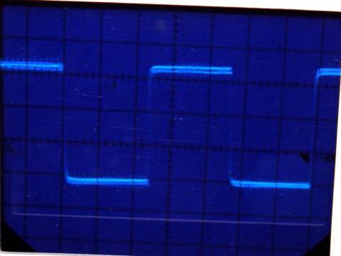
The square wave is generated by the scope for calibration, so I can't change its frequency
- Home
- Amplifiers
- Power Supplies
- Simplistic MosFET HV Shunt Regs