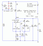
The 2sk170 is ok!
Vg Irf840=0,01V
The 840 isn't opening? Is that one OK? Maybe a 8-12V Zener guarding its gate? Between ground and gate.
I looked for LEDs having known 1.7V on voltage. On mouser, only some red LEDs are rated 1.7V: LED, and this is the data sheet of one of those: http://www.kingbrightusa.com/images/catalog/SPEC/WP7104LID.pdf, so I wonder if I miss anything?
I usually prefer to use what I have on hand, and since I had lots of 2.1V LEDs, instead of two LEDs I used one LED and a resistor. The disadvantage is that one has to then optimize the value of the resistor. Perhaps it may work for you too though, if it ends up being problematic finding the 1.7V LEDs.
I'll try a new one.
Any news with debugging it? Tried a new 840, checked all semis connections and orientations? Meanwhile, I got a suspicion that may when over 300V, those little -400V PNPs are struggling somehow. So I just thought that if it will not work on you with a single driver BJT, you may utilize some leftover MPSA92s for a cascode so to cut the dissipation and Vce in half. As a solution, it is even faster. If, it will not try to oscillate.

Attachments
Hi Salas, Hi all!
I finis Salas shunt PCB, but my pCb is wrong, So I can sent them to you 5 gift now. I think I wil make it a gain, i sent it later for you!
Im very, very sorry about this PCb! Thank you!
You do well you check because people if with a PCB, don't think twice, they put it to work. And here is high voltage. So no letter bomb gifts for now fellas.
When cascoding 2 BJTs, wouldn't 2 KSP94TAs be as good as MPSA92s?
Normally yes. 300+ is unknown territory for the SSHV for now, you are pioneering.
Hello,
I've made a short making tests and now I can't fix the problem.
I've finished my IRFP9240 in some smoke.
Now a rebuild the circuit with 10M45 as CCS and I'll test your new shunt with my bench PSU (only 330V) to avoid more smoke.
Ciao
Guglielmo
Single 10M45 will do. Whatever you have in hand. We have to debug the reg section for 300+. If it ends up OK and the problem area is finally addressed, a depletion cascode opportunity is just 2 10M45 and 3 resistors, for enhanced performance. But lets see first. Maybe the current gets less than predicted in the driver section. You can PM me when you go step by step in your new experiment, so we can think together even. We got to stabilize a 300+ ver for everybody to have access too. Its not too common, but Joshua needs one too for now at least.
Hello Salas ,
the 10M45 work perfect and I can trim easily from 10 to 70mA.
I think to make tests at 15mA, I think is safer for parts.
10m45 cascode in my experience is super noisy, better DN2540 in that configuration.
On the 2sk170 I've put a trimmer of about 500 ohm.
Seen your post I've put a pair of MPSA94 instead of MPSA92 I've a lot,.
I can use also IRF9610 instead of IRF840, at the moment I've only one left?
I want also to put a test point on every gate or base.
Tomorrow I'll be ready.
Ciao
Guglielmo
9610 is PMOS and 200V. Instead of 9240 yes, not instead of 840. That one is 500V NMOS. Maybe the other 840 is working too. We don't know yet. OK lets try to solve the circuit stable for 300+ Vout. Single 10M45 for start anyway. If it gets good we may evaluate a DN2540 casc CCS. But if all works well I would like to see if it works with 9610 etc that are universally available. PM me or send me an email during the course of the experiments so we try together if you like. When we see where was the trouble and we have a reliable fix, we will post just one schematic, not to confuse.
Well, parts for 340V stabilized are ordered. It may take up to two weeks for the parts to arrive and another day or two to build and test it. However I have all the measuring equipment and skill to debug it, in case anything may go wrong. I'll start with the schematic posted on message #859. Should anything go wrong, I'll try Salas's idea on post #907. Should it work properly, first I'll try to remove the 150V Zener diode and than the 30V Zener diode, to see whether any of them is really necessary. Sorry I wouldn't be able to shed any light before that.
- Home
- Amplifiers
- Power Supplies
- Simplistic MosFET HV Shunt Regs
