I got to listen to the HV shunt late last night, background is "blacker", overall sound is faster without harshness, voicing and timber has improved. I'm running one per channel in the line stage. Needless to say the Lambda No. 28 is now up for sale. Didn't think anything would beat the LCLCLC filter and the No. 28. I have tried the Allen Wright SuperReg and the Janus, both have ICs. While both are very good, I prefer the KISS approach and it does sound better. Anyone who is looking for a GREAT simple shunt regular, this IS the way to go. Again a big "thanks" to Salas.
Just started going through my parts bin to collect parts for a hv shunt build (over xmas?) and checking what will have to be ordered.
I am having a bit of a hard time determining the size of the mosfet heatsinks...(my application B+ ~200V max at 36mA).
Trying to read up on the subject turns up very scientific explanations at great lenght, but sure there is some handy formula for this...
Will a heatsink with 2.5K/W be enough (120x32x50mm)??
inertial
The Lambda No. 28 is a vintage labratory tube p/s regulator from the 50s (lambda is still producing lad grade p/s). Kind of like the Kepco. I was going to post it in the marketplace, once I found the documentation and schmatic. Email me and I can send you a picture and I will dig through my files to find the docs.
Compaired to the Salas HV shunt, it is more conjested sounding, not as fast, not as "black" in the background. The fact that it is a series regulator, puts a lot of components in the HV rail, along with the all the inductors and caps, muddies up the HV rail (all that inductance and phase shift from the caps).
My line stage (type 340 DHT, CCS, parafeed OPT) is very revealing and dependant on a clean, stable, low noise and low inpeadance supply. Because it has a high plate resistance, I wouldn't even try to run this tube without the CCS and parafeed OPT, the typical resistance loaded, cap coupled output, just doesn't "sing". Give the Salas HV Shunt a listen.
Oh, thanks cygnus,
I understand. I have talked with my fiend and he is disponible to
make a Sala's prototipe circuit for me. Unfortunately he is very busy at the moment but he hope to find a bit of time to make it into acceptable time...........I hope the same!
cheers,
Paolo
I understand. I have talked with my fiend and he is disponible to
make a Sala's prototipe circuit for me. Unfortunately he is very busy at the moment but he hope to find a bit of time to make it into acceptable time...........I hope the same!
cheers,
Paolo
Just don't connect anything to it. Use a 15K 10W dummy load resistor across its output and measure the Vout DC Voltage with a simple DVM. Trim it for the Voltage value you need following my posted instructions. If the LEDS are glowing and the output voltage is what it is expected to be, it is surely working. Shut it down, disconnect the dummy load, connect the audio circuit to be powered, and listen.
Simplistic PCB
I am thinking of trying this shunt regulator and have taken a crack at my first pcb layout. I am using the ExpressPCB software. I would appreciate your comments/corrections.
I am a bit unsure about the how much space to allow for the heat sinks - I have them mostly hanging off the sides of the board. My application will be for ~72 ma @ 250 volts output.
Thanks for any guidance.
Attachments
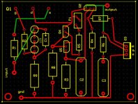
Gate resistors R2,R7 must be very near to the gates and better be carbon composition. If there is enough copper track between them and the gates, the track's self inductance defies their purpose.
You are going to run the CCS for 72mA, but how much will your actual load consume? Deduct that from the constant current and multiply what is left with your nominal Vout. That is your final dissipation that defines the shunt Mosfet sinking needs. The first CCS Mosfet will dissipate (Vin-Vout)*ICCS. Use 300V DC input. The difference to your 250V out is enough, more is going to create extra useless dissipation on the CCS Mosfet. In general I would keep the Mosfet pads very near the edge, on a common side, and full apart, so I could bend them for a big common heatsink parallel to the PCB or attach them to various upright sinks, common or individual ones. Also if the box is metallic with rather thick material, it may well serve the heat sink purpose, in moderate dissipation situations. In one of my low voltage NJFET RIAA boxes, which are small and thin, the box floor serves that purpose for 6.5W in total and it just gets very slightly warm. Off course we are talking high voltage here in your case, and I am not sure about the Mosfet insulation back pads security in the long run. If it is guaranteed and there is a fuse maybe OK. For total safety it is maybe better to use purpose heat sinks that don't touch the case.
You are going to run the CCS for 72mA, but how much will your actual load consume? Deduct that from the constant current and multiply what is left with your nominal Vout. That is your final dissipation that defines the shunt Mosfet sinking needs. The first CCS Mosfet will dissipate (Vin-Vout)*ICCS. Use 300V DC input. The difference to your 250V out is enough, more is going to create extra useless dissipation on the CCS Mosfet. In general I would keep the Mosfet pads very near the edge, on a common side, and full apart, so I could bend them for a big common heatsink parallel to the PCB or attach them to various upright sinks, common or individual ones. Also if the box is metallic with rather thick material, it may well serve the heat sink purpose, in moderate dissipation situations. In one of my low voltage NJFET RIAA boxes, which are small and thin, the box floor serves that purpose for 6.5W in total and it just gets very slightly warm. Off course we are talking high voltage here in your case, and I am not sure about the Mosfet insulation back pads security in the long run. If it is guaranteed and there is a fuse maybe OK. For total safety it is maybe better to use purpose heat sinks that don't touch the case.
Salas,
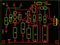
Thank you for the very clear explanation and suggestions. I had forgotten the the function of R2 and R7 were gate stoppers - I've moved these closer to the gates.
Interesting options you have outlined regarding the layout and positioning of the sinks. Given the voltages involved, I'm inclined not to use the chassis as a sink. I'll fool around with the layout a bit more.
In calculating the dissipation of Q3, would I use 250v*72ma.
Sorry about the newbie-ish questions, and thanks again for the help.
What is that 72mA? The actual consumption needs of your circuits to be powered? Or the current that you are planning to run the CCS? In general, set the CCS current at double the actual audio channels consumption needs. That will contain the dynamics OK with conservative dissipation on the PSU Mosfets.
What is that 72mA? The actual consumption needs of your circuits to be powered?
Yes.
- Home
- Amplifiers
- Power Supplies
- Simplistic MosFET HV Shunt Regs