Dear Salas,
Assume the master regulator retain in the power supply, what would happen if replacing the slave regulator (the one close to signal path) with your SSHV2?
What the differences between slave regulator and your SSHV2 for this application?
Thanks!
If done well with no oscillations and no additional interference noise, then some subjective differences between series with chip and a simple shunt I would guess. Don't try that without a scope.
Its little CCS range for Q1 & Q2 nonetheless. They usually go up to about 100mA in this arrangement. Measure R5. Is it 10R indeed? If no and its higher by mistake restore to 10R. If yes its 10R, weird CCS result if so, try 1R (1mV=1mA TP). Also check if R4 trimmer & R3 resistor are good.
All CCS measured good: resistors, trimmer, semis & diodes.
Changed 10R for 1R and now can reach 30mA but max Vout is 107V wiuth 4K7 dummy load.
Salas I bought my DN2540 to RS Amidata but the manufacturer says Microchip in place of Supertex, link to specs DN2540N5-G | MOSFET, DN2540N5-G, N-Canal, 500 mA, 400 V, Reduccin, 3-Pin, TO-220 | Microchip
![WP_20170224_002[1].jpg](/community/data/attachments/550/550828-48a79c3d1c4449c05ce308e61456cc41.jpg)
![WP_20170224_003[1].jpg](/community/data/attachments/550/550846-1b460074e0901c51af6cb83326f941c4.jpg)
Not, the problem is AZ1 hybrid graetz with two UF4007, as you know AZ1 needs the first cap max rated 60uF and not 200uF, also I don't have clear if AZ1 needs more voltage on the anodes because data sheet tell 2 x 300VAC to have 100mA and increasing voltage decrease intensity and I'm using 125V transformer so possible AZ1 is giving 125 or 150mA or more.
Attachments
Last edited:
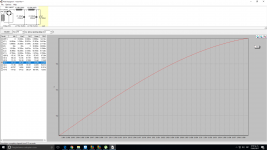
One picture speaks more than 1.000 words.
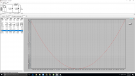
Now CCS
Used bridge UF4007 in place of AZ1 + two UF4007.
I've changed a Solen 10uF output capacitor on the SSHV2 with a ClarityCap CMR and the results are absolutely amazing. Forget bypassing (trust me I've tried everything including silver foils and teflons). ClarityCap CMR is THE capacitor to rule them all. However they are big so place has to be made either above or under the circuit board.
- Home
- Amplifiers
- Power Supplies
- Simplistic MosFET HV Shunt Regs