They all are from Salas's brain....knowledge....and we are trying to learn from him....this is as general and specific as you like....
The topic started out as general as power supply....and get specific as it goes along to be about a specific schematic....even within this specific topic, there are quite a few general discussions about it CCS design and applications, and may be other CCS (to be a bit more specific, the use of Salas's DN2540 CCS as anode CCS.....and the list may go on....if you like or dislike....)
My questions may seem a bit out of the norm here, but they are normal flow of exploration questions..... if we find it off topic in the future....we will start a new topic....or until the moderator tells to.
Until then, please do not limit our flow of thoughts trying to learn and make the best use of this specific schematic....
The DN2540 is a 150 mA device, so the answer is no.
N-channel power MOSFET [30V / 60A] ID: 355 - $1.25 : Adafruit Industries, Unique & fun DIY electronics and kits
Can the above be used, a N-channel power MOSFET 30V/60A ??
About what? Using a depletion mode Mosfet to make a CCS for heaters? Those are usually under an Ampere capable. The high current ones are different mode, can not self set and the more current potent they are the more capacitive or "slower" they get. Catch 22. Use a capable 3 pin regulator in CC mode on a hefty sink if you must use regulated DC CCS heaters for some reason.
 ......
Thankyou Salas....you have mentioned this before....I have bought a pair of the SSLV board....but don't have time to put them together yet....I hope to start soon....and when I start, I will need to ask a few more questions again ( at the SSLV1.1 build & fairytales...) thanks in advance....
Only 0,2A for spare? It is a way to disaster. Cold tube heaters have 3-5 times less resistance and so - need 3-5 times more initial current to make heat. Depending on the tubes - it is greatly possible they won't be making heat at all!
Making such complicated circuit for the non-signal part of the device seems overkill.
By the way, the heaters itself are sort of constant current devices. The more current - the more heating - the more resistance - the less current...
Making such complicated circuit for the non-signal part of the device seems overkill.
By the way, the heaters itself are sort of constant current devices. The more current - the more heating - the more resistance - the less current...
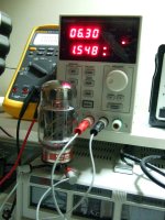
Just for fun I lit up a KT-88 Genalex (Russian reissue). I set the bench PSU at 1.6A CC mode & 6.3V. Those numbers are in its spec-sheet.
It does as expected. I.e. it lights up gradually by dipping the voltage until it meets 6.3V in 30sec and its fully lit & stable in a minute. If I don't set a CC limit it kicks at 2.4A instantly and comes down fast while the voltage is always 6.3V. It takes about the same time to fully shine through the plate holes and stabilize at ~1.550A as in the first case anyway.
It does as expected. I.e. it lights up gradually by dipping the voltage until it meets 6.3V in 30sec and its fully lit & stable in a minute. If I don't set a CC limit it kicks at 2.4A instantly and comes down fast while the voltage is always 6.3V. It takes about the same time to fully shine through the plate holes and stabilize at ~1.550A as in the first case anyway.
Attachments
I did not say that in such refined case it would not work. I think if you got some directly heated tubes or a bunch of several smaller or different-current tubes - you can easily reproduce the problem (I did it for 4x 12AX7 + 2xKT-88 with such problem).
According to your experiment: the current/voltage was stable in 30sec in first case and "almost instantly" in the second. The amount of energy passed was definitely much lesser in the first experiment for "about the same time" of lighting. It means that something was wrong in the experiment.
According to your experiment: the current/voltage was stable in 30sec in first case and "almost instantly" in the second. The amount of energy passed was definitely much lesser in the first experiment for "about the same time" of lighting. It means that something was wrong in the experiment.
Poty, nothing could be wrong in such a simple demonstration. Its only natural.
When we set a current limit to the tube it will just pull back on initial transient energy. What workload is to be done for the heater turn on cycle its just done in longer time.
The peak is momentary and the decline rapid. So "about" has an impact.
If it could be done with auto data log it sure will show the same energy spent in two different curve/time cycles, else it would not end up with same constant voltage and same current draw.
For mixed current draw heaters system you mention, constant current drive is not applicable, and constant current limit is to be tuned experimentally when using one. Its understood that we talk CC limit and not CC drive in the experiment.
Only 0,2A for spare? It is a way to disaster. Cold tube heaters have 3-5 times less resistance and so - need 3-5 times more initial current to make heat. Depending on the tubes - it is greatly possible they won't be making heat at all!
Making such complicated circuit for the non-signal part of the device seems overkill.
By the way, the heaters itself are sort of constant current devices. The more current - the more heating - the more resistance - the less current...
Yes, running the heater circuits from a CCS is a valid way to get the heaters to operate very consistently.They will just light up gradually. Try with a CCS and no spare even, to see for yourself.
Poty, nothing could be wrong in such a simple demonstration. Its only natural.
When we set a current limit to the tube it will just pull back on initial transient energy. What workload is to be done for the heater turn on cycle its just done in longer time.
The peak is momentary and the decline rapid. So "about" has an impact.
If it could be done with auto data log it sure will show the same energy spent in two different curve/time cycles, else it would not end up with same constant voltage and same current draw.
For mixed current draw heaters system you mention, constant current drive is not applicable, and constant current limit is to be tuned experimentally when using one. Its understood that we talk CC limit and not CC drive in the experiment.
by definition, a CCS will change its terminal voltage in order to maintain current, so cold resistance of a tube is no problem, in fact better than a constant voltage source which is more problematic in terms of cold resistance...
another way is to series an NTC resistor to soft start the heaters, in some cases i even used power resistors....
by definition, a CCS will change its terminal voltage in order to maintain current, so cold resistance of a tube is no problem, in fact better than a constant voltage source which is more problematic in terms of cold resistance...
Real example. 12AX7A marked as Lafayet has room temperature resistance of 3.3Ohm in the 6.3V mode. It's current after the stabilization is 290мА@6.3V (resistance is 21,72Ohm).If it could be done with auto data log it sure will show the same energy spent in two different curve/time cycles, else it would not end up with same constant voltage and same current draw.
Powering by 6.3V regulated PS we have initial current of 6.3/3.3=1.8A. It further drops to 290мА.
Powering by CCS with nominal current of 300mA we have initially 0.3*3.3=0.99V. After the stabilization we have slightly more than 6.52V.
This REAL case shows us that:
1. the constant current supply is far from natural;
2. the energy passed to the heater is higher in the constant voltage mode (always higher up to stabilizing point) than in the constant current mode (always lower up to stabilizing point). Salas, your assumptions are wrong. It seems you confused energy with power (the amount of energy consumed per unit time).
3. if the amount of power radiating to environment is more (at initial stages) than the amount of supply power you'll never have the heaters lit.
Continuing the example: different flawors of 12AX7s can have from 270 to 360mA of tolerance margins. Using CCS we'll have as much as 7V to 5,25V difference. Is it normal?
By the way, relating KT-88. Sovtek KT-88 has nominal current of 1.7+/-0.1A, GEC KT-88 - 1.6+/-10% (+/-0.16A). So, the real current consumption of KT-88 can be 1.8A - this will dry up your planned reserve of 0.2A fully.
Even simple demo should have proper explanations. In this case you chose wrong indicators of stabilization and make the conclusion that both methods led to the same result (in time periods).Poty, nothing could be wrong in such a simple demonstration. Its only natural.
When we set a current limit to the tube it will just pull back on initial transient energy. What workload is to be done for the heater turn on cycle its just done in longer time.
In your experiment it means the same.Its understood that we talk CC limit and not CC drive in the experiment.
- Home
- Amplifiers
- Power Supplies
- Simplistic MosFET HV Shunt Regs