Bravo stixx, well done!
BTW, I would have thought the aikido is already a ripple remover, but now you got a regulator too. Your sound might improve with a single ended design? There are quite a few extra parts in the aikido that do nothing else but clean up dirty supplies. Now you got salas clean supply")
Edit: in other news, the high powered salas shunt is still not working. It oscillated from the beginning like crazy. I will try once more with fresh parts and if it doesn't work, will call it quits for now.
John, for such a low parts project I would go point to point soldering.
BTW, I would have thought the aikido is already a ripple remover, but now you got a regulator too. Your sound might improve with a single ended design? There are quite a few extra parts in the aikido that do nothing else but clean up dirty supplies. Now you got salas clean supply
Edit: in other news, the high powered salas shunt is still not working. It oscillated from the beginning like crazy. I will try once more with fresh parts and if it doesn't work, will call it quits for now.
John, for such a low parts project I would go point to point soldering.
Hey Karsten,
thank you for your always kind words!
Making mistakes or screwing up just teaches you another lesson, and finally achieving something working and good sounding is very rewarding in this hobby...
Will keep you posted once I get to case the Aikido up and try the AE transformers.
best,
Oliver
thank you for your always kind words!
Making mistakes or screwing up just teaches you another lesson, and finally achieving something working and good sounding is very rewarding in this hobby...
Will keep you posted once I get to case the Aikido up and try the AE transformers.
best,
Oliver
Thanks 'flexer for the kind words!
Yeah, it is said to have great PSRR but still needs a decent psu.
I have gone from a passive CRCRC over the quick Maida to the Salas shunt, and man can I tell you it is a difference!
The level of detail is absolutely fascinating...
Next amplifier will be an SE-spud with output transformers using pentodes like C3G, D3A or 7788. The shunt regulator was intended for this new project but I couldn't wait to try it out so I used my Aikido as test bed. You know the rest of the story...
BTW, I would have thought the aikido is already a ripple remover, but now you got a regulator too.
Yeah, it is said to have great PSRR but still needs a decent psu.
I have gone from a passive CRCRC over the quick Maida to the Salas shunt, and man can I tell you it is a difference!
The level of detail is absolutely fascinating...
Next amplifier will be an SE-spud with output transformers using pentodes like C3G, D3A or 7788. The shunt regulator was intended for this new project but I couldn't wait to try it out so I used my Aikido as test bed. You know the rest of the story...
Congratulations Stixx! Thanks for your invitation errr...for beer!
Ikoflexer: No way you will remain without an HV shunt for your particular power needs. Email me and we will try more on the fresh idea of the high powered one. You have many non standard parts, and you power a whole amp. There must be interactions. We will analyze the set up, and see what we will come up with.
Ikoflexer: No way you will remain without an HV shunt for your particular power needs. Email me and we will try more on the fresh idea of the high powered one. You have many non standard parts, and you power a whole amp. There must be interactions. We will analyze the set up, and see what we will come up with.
salas, I didn't mean to say I will give up for good. I usually take a little break to regroup my forces Then attack again. At the moment I was playing with some ideas on getting it rock solid and stable, in simulation. Will mail you.
Oliver, interesting that you mention the spud amp; that's what the high current regulator I'm trying to build is for, a one tube spud amp using the 6LU8 tube. It sounds great already, even without a regulator, and is simple to build. My experience with the aikido comes from using the aikido idea in a tube buffer I'm using just before the lm3886 chipamp. I was playing with the aikido idea in simulation, and inserted a AC component in the supply. Adjusting the values of the aikido resistors (you will notice that after each stage there are two tubes doing the aikido supply cleaning bit) can get the AC component of the power supply to microvolt level, works like an embedded regulator. However, after discovering the salas regulator, I would rather do regulation outside the amp stages. Just my 2c.
Then attack again. At the moment I was playing with some ideas on getting it rock solid and stable, in simulation. Will mail you.Oliver, interesting that you mention the spud amp; that's what the high current regulator I'm trying to build is for, a one tube spud amp using the 6LU8 tube. It sounds great already, even without a regulator, and is simple to build. My experience with the aikido comes from using the aikido idea in a tube buffer I'm using just before the lm3886 chipamp. I was playing with the aikido idea in simulation, and inserted a AC component in the supply. Adjusting the values of the aikido resistors (you will notice that after each stage there are two tubes doing the aikido supply cleaning bit) can get the AC component of the power supply to microvolt level, works like an embedded regulator. However, after discovering the salas regulator, I would rather do regulation outside the amp stages. Just my 2c.
Salas said:Weirdly (?) it still responds subjectively for Stixx on different PSUs and regs.
Sorry, I don't understand what you're referring to.
quote: Originally posted by Salas Weirdly (?) it still responds subjectively for Stixx on different PSUs and regs. Sorry, I don't understand what you're referring to.
Guess he meant to say that my Aikido sounds different on different psu's...
Wouldn't call it weird though because even with good PSRR it won't filter out everything...
And the blacker the background (--> Pitchblack) the more detail you have...also very noticeable the improvement in soundstage...like 3D around my head.
Objectively
Yes, I was referring to the Aikido and its inbuilt PSRR main theme. But its not only PSRR. The output impedance of the reg up high, the way it passes or gets excited by rectification byproducts, etc etc. The proof is in the pudding as they say. A system from wall plug to headphones or to speakers and room, does the Job? If yes, cool.
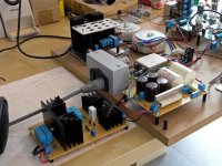
Stixx said:pic for the ones interested...
Wow! Very Meccano! I like!
Stixx said:pic for the ones interested...
Neat setup, literally!
Beautiful Stixx !!!!!
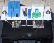
This is my build of salas shunt.
Tests will be done in the weekend.
Transformer will be an existing 240V sec 50VA, SS Bridge, 47u + 4 x 500R/47u RC blocks. According to PSII that means 150V (approx.) input for the shunt.
My real load will be around 50ma. Salas, do you have any suggestion for the value of the ballast resistor ?
Attachments
Marinos,
your built easily qualifies for the most compact stuffing of the board, respect!
My next version will also be a bit tighter but I want to retain two individual heatsinks...just had a very long look on GaryP's layout today.
According to Ohm's law your ballast resistor should be around 2K (next common value) of heatsinked 15W resistor.
Marinos said:Salas, do you have any suggestion for the value of the ballast resistor ?
As Stixx said. Nice compact layout BTW. Make sure that the 840 is really electrically insulated from the sink before you fire it up.
Success
In 144V out 90.
Remarks:
- 15K 5W Led bias resistor becomes very hot
- measuring voltage drop at the last psu RC shunt is working at 113 ma
- Nearly everything is running hot... Relatively small changes to load current and/or input voltage give serious changes to dissipation, so amateurs like me should be careful
I know we're all adults and all that, but I would like to remind everyone that we're dealing with deadly voltage values here. Please take a moment to review your practices:
* keep a hand in the pocket
*don't forget that if you wear necklace it may drop onto the circuit when you're leaning over it to measure something
* capacitors hold deadly charges, so make sure you always use a bleeder resistor in the PSU, or discharge them with a resistor stuck to a piece of wood
* don't wear loose shirts/clothing
Be safe, it's only a hobby, not worth your life.
Edit: I may as well add something about the new shunt. First, Marino, congrats! My shunt runs hot too. The amp+shunt draws something like 220mA all in all. The shunt mosfet works happily at about 24W (measured), and it enjoys a good size heat sink, but I think I should use a larger one, because this one gets hot to touch. The CCS mosfet is barely warm. The scope shows an output trace which is basically a flat line at 226V DC.
Marinos said:Success
In 144V out 90.
Remarks:
- 15K 5W Led bias resistor becomes very hot
- measuring voltage drop at the last psu RC shunt is working at 113 ma
- Nearly everything is running hot... Relatively small changes to load current and/or input voltage give serious changes to dissipation, so amateurs like me should be careful
Congratulations!
Your report indicates a healthy shunt. Don't worry about the 15k, a cement resistor of that size always burns even if it dissipates only 1.4W in your case. Your common sink isn't that big but the Mosfets are tough. Since you probably got happier LEDs, you can save off a little current from the CCS if you make your R1 27R. This must roughly get you a little under 100mA. It may relax the
 enough.
- Home
- Amplifiers
- Power Supplies
- Simplistic MosFET HV Shunt Regs