hey all!
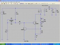
Am working on a self oscillating flyback smps. i get the schematics from smps handbook.
when i start simulating the circuit using LTspice it doesn't work
i couldnt generate the proper signal to fire the switching transistor.
could any one look at my schematic and help me..
i think its the values of the elements or somthing about the flyback transformer !!
and thanks in advance..
Attachments
Thanks for the replies..
due to the snubber capacitor C2 may be because i changed the values thousand times so may be i miss this one.. sorry
after i changed the switching transistor to IRF mosfet i got a switching signal but it still has a random behavior.
i will attach the simulation file to make it easier if anyone could help..
Attachments
Obviously, with your values, you arrrive at insane voltages and currents: when properly simulated, i.e. a time long enough for the initial conditions to settle, and a time step short enough, the voltage on the drain reaches over 330V.
Off course, it is practically unloaded, and there is no regulation.
Have you properly defined target values for the frequency, conduction time, peak current, output power, etc?
Where will you introduce the regulating/feedback element?
What regulation strategy will you use?
These are the prerequisites, and once they have been laid down, you have to design the circuit and calculate the values accordingly.
A more informal approach will not work.
I have substituted more realistic values, and now it works in a more sensible manner, but all the above-mentionned issues remain open.
I'll try to disguise the .asc file into a .txt. To use it, restore the correct extension.
Attachments
hey..
the circuit is low power and has variable frequency so i prefered to let these elements open..
and the regulation in the schematic am using has a feedback signal throw a shunt reglator (TL431) and opto coupler but i thought it is not necessary to complicate the circuit as
long i cant get a stable output voltage .
Try this ") The skip inital operating point solution should be turned off or else circuits like these might not start.
The skip inital operating point solution should be turned off or else circuits like these might not start.
The component values you chose gives a way too high frequency for this kind of circuit. My changed circuit optimally should have the inductances increased even further to give lower operating frequency.
The darlington/CFP is needed or the current trip point will change too much between oscillating mode and stopped mode making burst operation start at pretty high load levels.
The 470 ohm resistor makes the turn on/off pretty slow, this is why frequency should be kept low. The resistor could be reduced but watch out for high turn-off-transistor current and high zener current at high input voltage.
The skip inital operating point solution should be turned off or else circuits like these might not start.The component values you chose gives a way too high frequency for this kind of circuit. My changed circuit optimally should have the inductances increased even further to give lower operating frequency.
The darlington/CFP is needed or the current trip point will change too much between oscillating mode and stopped mode making burst operation start at pretty high load levels.
The 470 ohm resistor makes the turn on/off pretty slow, this is why frequency should be kept low. The resistor could be reduced but watch out for high turn-off-transistor current and high zener current at high input voltage.
Attachments
Try this
The component values you chose gives a way too high frequency for this kind of circuit. My changed circuit optimally should have the inductances increased even further to give lower operating frequency.
The darlington/CFP is needed or the current trip point will change too much between oscillating mode and stopped mode making burst operation start at pretty high load levels.
The 470 ohm resistor makes the turn on/off pretty slow, this is why frequency should be kept low. The resistor could be reduced but watch out for high turn-off-transistor current and high zener current at high input voltage.
How could you modify this circuit to work with 110V mains input?
Unless you are experimented enough with power switchers, you should use ready-made solutions like this one:
http://www.google.be/url?sa=t&sourc...gFokUNaXA&sig2=Wpzzhl2v_DcCICOj9MhcVA&cad=rja
Otherwise, you'll end up smoking component after component.
http://www.google.be/url?sa=t&sourc...gFokUNaXA&sig2=Wpzzhl2v_DcCICOj9MhcVA&cad=rja
Otherwise, you'll end up smoking component after component.
Unless you are experimented enough with power switchers, you should use ready-made solutions like this one:
http://www.google.be/url?sa=t&sourc...gFokUNaXA&sig2=Wpzzhl2v_DcCICOj9MhcVA&cad=rja
Otherwise, you'll end up smoking component after component.
I agree with you. However, I am actually trying to learn power supply design. I have built up some PSU around chips. The IC datasheet always tells you exactly which component to use. The design goal is to have 12V regulated up to 300mA. The switch frequency should be around 100kHz (only because that is what the transformer is nominally at).
I started with the SMPS Handbook just like the OP. I attached the design I am working on. The transistor doesn't turn on when R1 is 100k. It turns on around 30 volts DC when R1 is 2.2k. The output is regulated until the input voltage goes above 45 volts DC or so. Then the output creeps up in voltage. Does anybody know why this is happening? I obviously can't go to 170 volts because everything on the output would fry and the snubber would fry. Any other tips would be appreciated.
The file is a '.asc' file, just rename.
PS: The transformer I am using is a Coilcraft A9619-CL. http://www.coilcraft.com/ncp101x.cfm
Attachments
Last edited:
Self oscillating converters are the most difficult to design.I agree with you. However, I am actually trying to learn power supply design. I have built up some PSU around chips. The IC datasheet always tells you exactly which component to use. The design goal is to have 12V regulated up to 300mA. The switch frequency should be around 100kHz (only because that is what the transformer is nominally at).
I started with the SMPS Handbook just like the OP. I attached the design I am working on. The transistor doesn't turn on when R1 is 100k. It turns on around 30 volts DC when R1 is 2.2k. The output is regulated until the input voltage goes above 45 volts DC or so. Then the output creeps up in voltage. Does anybody know why this is happening? I obviously can't go to 170 volts because everything on the output would fry and the snubber would fry. Any other tips would be appreciated.
The file is a '.asc' file, just rename.
PS: The transformer I am using is a Coilcraft A9619-CL. Coilcraft Flyback Transformers for ON Semiconductor NCP101X
There are a number of problems, the main one being the mode of control you chose: the control transistor taps a significant amount of power from the transformer, and at light loads, this damps the oscillation and makes the converter operate in a highly discontinuous mode, more a bang-bang control in fact.
Situation can be improved by some modifications in the feedback circuit, making the converter a variable frequency one, the frequency being proportional to the load.
Attachments
Thanks for the feedback Elvee. I'll build this one up and see how it performs. I noticed you changed the transformer inductance. If I change the inductance back to the Coilcraft inductance, will the circuit still perform as desired? I'd like to use this transformer because it is what I have available in the lab.
I think it is too early to go physical: there is still a lot of work to be done to explore all of the functionning enveloppe.Thanks for the feedback Elvee. I'll build this one up and see how it performs.
These circuits can be incredibly tricky, and I just gave you a lead
No, it will take much more power with the original inductance, and the larger signal will push it harder in the discontinuous mode.I noticed you changed the transformer inductance. If I change the inductance back to the Coilcraft inductance, will the circuit still perform as desired? I'd like to use this transformer because it is what I have available in the lab.
It is certainly possible to accomodate the high feedback voltage, but there is work to be done to do so, and that is your quest...
A possible design path is to first create a non-servoed power oscillator, delivering ~150% of the nominal power in free running mode, adjust the operating parameters to get to the desired the target frequency, etc, then add a feedback that influences the parameter you chose for the control: e.g. frequency, duty cycle, ON period, or other.
I advise you reverse engineer a small switching AC to DC adapter to get an idea at how things are done.
- Status
- This old topic is closed. If you want to reopen this topic, contact a moderator using the "Report Post" button.
- Home
- Amplifiers
- Power Supplies
- self oscillating flyback smps