luka said:Hi
With same components you will have shorter delay, because there will be higher C charging current, but you then change resistor after rectifier.
You have limited current that charges C and relay, so C can't be charges fast. Why only 40, I think you will be better with 1k?
If you will simulate circuit, put all components in, like that 0.12uF and 230Vac if this is what you use...
I did simulated it using the all the components. using 240VAC -> .47uF -> 500ohm -> bridged rectifier -> 2.2mF -> 1.1kohm (coil resistance).
same thing happened. instanteously charging up of 2.2mF without the 40.
but this is just simulation. sometimes real life is different.
Luka, can you please measure the coil resistance if possible?
Thank you very much
")
Hi,
I am not in favour of these rising voltages triggering a relay.
The voltage and current sent to the relay have to be high enough to ensure reliable triggering when supply voltage is at it's lowest.
This demands a much higher operating voltage and current on the relay when voltage is normal or above nominal.
The circuit currents can be much higher than expected and everything runs hot or very hot.
I recommend transformer power.
I also recommend transistor (or FET) triggering of the relay.
Use an electrolytic across the transistor and relay series combination. Add a resistor in series with the relay+transistor to reduce operating current. If the supply were 20V then a 12V relay would see near 20V across the cap when the transistor fires and then the resistor reduces the operating voltage to about 9V. everything runs much cooler and the relay triggers very quickly when the delay has timed out (no chattering as the relay thinks about triggering).
Hi
It is 2.13k with that resistor in parallel.
I don't know why you want to use .47uF, if you should use something like .22uF
What is your coil resistance?
I have made my simulation, and this is what I used
240Vac, 220nF, bridge rectifier, 1k,1000uF, relay(2.08k resistance) and 10k in parallel with coil
It works below 200Vac, and you get delay of about 2s at 240Vac
Hi Luka,
thanks.
A timing variation of 1.6S to 2.2S is not bad over that range of input voltage.
A range of 21.3V to 25.1V as operating voltages should not concern a 24V relay.
For a resistor soft start you can reduce the delay to as little as 300mS.
This would allow the 1mF timing cap to be reduced to about 330uF giving about 0.5S to 0.7S delay before the relay shorts out the soft start resistor.
Sorry guys, but why you looking for complex solution, if simpler one does exist? The trick is ok about 2years
http://www.diyaudio.com/forums/showthread.php?s=&postid=709895&highlight=#post709895
http://www.diyaudio.com/forums/showthread.php?postid=696907#post696907
http://www.diyaudio.com/forums/showthread.php?s=&postid=709895&highlight=#post709895
http://www.diyaudio.com/forums/showthread.php?postid=696907#post696907
Hi Ivx and others wanting to listen,
Thermistor (or similar) don't work for all conditions.
eg. repeated brownouts at seconds intervals.
Loss of power for seconds.
A Thermistor in line varies the voltage allowed through to the load.
I just tested an amplifier, with a weird characteristic showing on the scope. The max AC voltage on the load showed a clip very soon after applying the load. Then the clip started to "dissappear" and a higher maximum output became available.
It took a while to realise it was the temporary rig up using the Thermistor soft start that was modulating the supply voltage to the main transformer. Ametherm MS15 15004 into 1kVA toroid on 240Vac.
I intend using only relay bypassed resistor soft start. They are reliable and predictable and allow better performance from the amplifier.
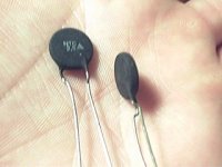
There are special NTCs intended for soft start and they work fine. For higher power applications mount several of the lower resistance high current types in series and bypass them with a relay after 200ms or so...
For example, In one SMPS producing over 2KW I'm using four EPCOS B57236S259M in series (4*2.5=10 ohms) to inrush-limit a 4x470uF capacitor bank (1880uF) fed directly from rectified mains. I think that this application is well within specs according to the datasheet, as the maximum allowed capacitance for one of those NTCs at 230V is just 200uF, but this figure seems to increase with the number of series NTCs squared, yielding 3200uF for 4 NTCs.
Datasheet:
http://www.epcos.com/inf/50/db/ntc_06/ICL__B57236__S236.pdf
A relay fed from an internal 12V housekeeping (fan) supply bypasses the NTCs as soon as the SMPS comes up. I think that this approach is more tolerant to failures than the traditional relay-and-plain-resistor because the NTC effect prevents huge dissipation in case the relay does not close. Also, it responds better to power cycling than a plain NTC because the relay keeps the NTCs bypassed and cool during normal operation.
Attachments
luka said:HI
But you can't limit current to 0.5A at startut, then pass 16A through... Not with one...
Hm, but you can't too (500Ohm for 240VAC?), especially for pure class A.
Eva, someone once told me about customised NTC, which can drop from 50Ohm to .1Ohm, but the stuff has pretty big size.
but I can, and it works, if the resistor is chosen appropriately.IVX said:..... but you can't too (500Ohm for 240VAC?), especially for pure class A....
5 off 10r 5W in series =50r 25W.
Feeding a 1kVA transformer, 240Vac:37+37Vac, charging 150mF to 51Vdc and bypass relay delayed 500mS or so, with instant off.
Protects the repeated start up situation admirably and is cheap and easy using a 555 timer.
This works whether it's for ClassA (Krell Klone Ksa1000) or ClassAB dual mono Leach clone (charging 180mF to 58Vdc)
Oh, the mains fuse in both cases is just T3.1A (about 750W) and survives repeated start ups. I suspect I could go lower but there is little incentive to try T2A or T2.5A, maybe some day.
You are missing the point luka. You need the series resistance to be low enough in order to allow the capacitors to charge to a voltage close to t the steady state value before the relay closes, while the load is attached. Also, the impedance has to be low enough to allow the magnetic flux in the transformer to become balanced before the relay closes. Here is where NTCs come handy because their resistance ramps from a few ohms to a few dozens miliohms as they get hot during the brief startup period.
- Status
- This old topic is closed. If you want to reopen this topic, contact a moderator using the "Report Post" button.
- Home
- Amplifiers
- Power Supplies
- help with inrush limited circuit from EDN