
Related to the mechanical part it depends on your milling skills and possibilities. The slot for the magnets is a must, one way or the other.
About the magnetic part. What frequency range do you want to cover?
At the lower frequency end you need to know the maximum excursion.
The width of your voice coil + the PP excursion must be at least the width of the lineair flux area. Does it fit in 8 mm?
If not you get non lineair distortion!
I will try to make it less complex.
If there's someone who wants to fiddle with the FEMM files.
Let me know and I'll post them.
Henjo

Hi Henjo,
I want to cover 250-18000 or 20000hz, the movement +-2mm, and i think and hope that 0.16mm diam copper wire would be just fine. What do you say about this?
I want the femm files to try next week wen i'll come back home to try to figure how this progr works..
Thank you
Sergiu
Till then this is what i'm enjoying right as we speak. I also read the post. Its a total relaxation.
Attachments

Last edited:
Here's your answer:
3% benefit in flux density and 2 mm less lineair excursion.
It's up to you.
View attachment 492193
Henjo
Henjo you are right, there is not so much to gain from 8mm... Now i have readed everything.. My goal was to increase as much as possible the flux without saturation. I have two 15"woofers (paper suspension)wich i want to use in a sealed enclosure combined with these Janus 50 speakers. I want to cut the woofers at 250-300hz first order filter so i think that i will need between 2-3 mm excursion so that the mid bass doesnt sound thin..
You are right Henjo, i think i dont need more than 96-98dB for my project..
What do you say if i use thicker plates, of 12mm and machine them down to 10 mm on the edges, will i beat 1,35T in a 3mm gap. Im curious. If this works i will use it and if not i will stick to the 10mm plates an 1.3T.
Can you simulate this scenario please?
Kind regards
Sergiu
Last edited:
hmmm i was at the art shop yesterday looking for paper. i found some japanese paper wich was really light BUT did not hold form relaly well so not rigid, i ended up with only low end ") then i used some liquid glass to harden it and a heater to let it dry... dumb me my metal heated up pretty high, i hope i did not wrkecked my magnets. at least one of them came lose end ended up in the magnet gap... i then had a verry hard time to get the 4 metal rods from eacht other . so i guess i did not demagnetised them with the heat, but it whas close , since it felt pretty warm to the touch.
then i used some liquid glass to harden it and a heater to let it dry... dumb me my metal heated up pretty high, i hope i did not wrkecked my magnets. at least one of them came lose end ended up in the magnet gap... i then had a verry hard time to get the 4 metal rods from eacht other . so i guess i did not demagnetised them with the heat, but it whas close , since it felt pretty warm to the touch.
But what i wanted to say whas this, i also found some balsawood, ranging from 40kg to 200Kg /m3 devide it by 1000mm it comes around 40grams to 200 grams /m2 thats in paper range even when it is 1mm thick. i could even cnc slits in it to increase bending and half the size near the coil to 0.5 mm or even lower. it is by FAR more rigid then any paper of this weight. it then is more easy to center in the gap, and still weighs less then 2 pieces of normal coppy paper of 80 grams sandwiching the coil.
this stuff is so weird. if you rgab a 1x100mmx1000mm piece it weighs almost nothing. downfall is i did not find a biiger piece then 100 wide. but i recon you could pretty easy glue them together, with some cnc tricks
or put some sort of foam in between seperate pieces to decouple them from each other and get resonances at a diferent freq, aaah well maybe it does not work at all you never know, i think some loudspeakers used balsa or bamboo cones.
then i used some liquid glass to harden it and a heater to let it dry... dumb me my metal heated up pretty high, i hope i did not wrkecked my magnets. at least one of them came lose end ended up in the magnet gap... i then had a verry hard time to get the 4 metal rods from eacht other . so i guess i did not demagnetised them with the heat, but it whas close , since it felt pretty warm to the touch.But what i wanted to say whas this, i also found some balsawood, ranging from 40kg to 200Kg /m3 devide it by 1000mm it comes around 40grams to 200 grams /m2 thats in paper range even when it is 1mm thick. i could even cnc slits in it to increase bending and half the size near the coil to 0.5 mm or even lower. it is by FAR more rigid then any paper of this weight. it then is more easy to center in the gap, and still weighs less then 2 pieces of normal coppy paper of 80 grams sandwiching the coil.
this stuff is so weird. if you rgab a 1x100mmx1000mm piece it weighs almost nothing. downfall is i did not find a biiger piece then 100 wide. but i recon you could pretty easy glue them together, with some cnc tricks
or put some sort of foam in between seperate pieces to decouple them from each other and get resonances at a diferent freq, aaah well maybe it does not work at all you never know, i think some loudspeakers used balsa or bamboo cones.
Last edited:
Henjo you are right, there is not so much to gain from 8mm... Now i have readed everything.. My goal was to increase as much as possible the flux without saturation. I have two 15"woofers (paper suspension)wich i want to use in a sealed enclosure combined with these Janus 50 speakers. I want to cut the woofers at 250-300hz first order filter so i think that i will need between 2-3 mm excursion so that the mid bass doesnt sound thin..
You are right Henjo, i think i dont need more than 96-98dB for my project..
What do you say if i use thicker plates, of 12mm and machine them down to 10 mm on the edges, will i beat 1,35T in a 3mm gap. Im curious. If this works i will use it and if not i will stick to the 10mm plates an 1.3T.
Can you simulate this scenario please?
Kind regards
Sergiu
250hz first order is a bit to much to ask i guess. you will only be down 12 db at 62.5hz.
i hope it will handle that
Hi Wrinex,
You are right Rullit did some balsa cones.
retro vintage modern hi-fi: Atelier Rullit Projects
Glow made some cones of bamboo fiber.
Full range speakers single driver extended range bamboo. Glow speakers full range speakers single driver orb shaped loudspeakers recycled scrap wood enclosures hemp
Another way to fight the resonances is cut some slits in the paper at the outer half of the membranes on strategic places. Something like Scanspeak does in their revalator series.
Br,
Henjo
yeah i think vandersteen has balse cone composite, and jvc as well
glow heavy heavy heavy smoothing
http://www.glow-audio.com/i/spkr/V1specs.jpg
glow heavy heavy heavy smoothing
http://www.glow-audio.com/i/spkr/V1specs.jpg
You are right Henjo, i think i dont need more than 96-98dB for my project..
What do you say if i use thicker plates, of 12mm and machine them down to 10 mm on the edges, will i beat 1,35T in a 3mm gap. Im curious. If this works i will use it and if not i will stick to the 10mm plates an 1.3T.
Can you simulate this scenario please?
Kind regards
Sergiu
Hi Sergui,
I think it not necessary to use thicker steel.
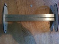
What is necessary is to use your magnets 90° rotated to have an effective area 400 mm2. (see picture)
In the cuurent model you doný need to mill a slot in the steel strip.
The magnets are sliding between de square aluminum rod and the 5x30 aluminum end strip.
The magnet wire as simulated is 0,224mm (AWG 31) backlack.
Kupfer-Backlackdraht 0,224 mm, lötbar, TI 180 °C, 100 g - Menting Mikroelektrik
With a coil of 18 windings and Janus 50 it is app. 8 Ohm.
I simulated with and without counter magnets. The difference in nihil.
BR,
Henjo


Hi Sergui,
I think it not necessary to use thicker steel.
What is necessary is to use your magnets 90° rotated to have an effective area 400 mm2. (see picture)
In the cuurent model you doný need to mill a slot in the steel strip.
The magnets are sliding between de square aluminum rod and the 5x30 aluminum end strip.
The magnet wire as simulated is 0,224mm (AWG 31) backlack.
Kupfer-Backlackdraht 0,224 mm, lötbar, TI 180 °C, 100 g - Menting Mikroelektrik
With a coil of 18 windings and Janus 50 it is app. 8 Ohm.
I simulated with and without counter magnets. The difference in nihil.
BR,
Henjo
View attachment 492522
View attachment 492523
View attachment 492524
nice sim!! but this means it gets twice as expensive ?
with this wire power handling will be pretty good, but how about frequency response, its a decent amount of copper?
Last edited:
Hi Sergui,
I think it not necessary to use thicker steel.
What is necessary is to use your magnets 90° rotated to have an effective area 400 mm2. (see picture)
In the cuurent model you doný need to mill a slot in the steel strip.
The magnets are sliding between de square aluminum rod and the 5x30 aluminum end strip.
The magnet wire as simulated is 0,224mm (AWG 31) backlack.
Kupfer-Backlackdraht 0,224 mm, lötbar, TI 180 °C, 100 g - Menting Mikroelektrik
With a coil of 18 windings and Janus 50 it is app. 8 Ohm.
I simulated with and without counter magnets. The difference in nihil.
BR,
Henjo
View attachment 492522
View attachment 492523
View attachment 492524
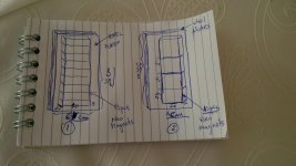
Hi Henjo,
What do you mean when you say about reorientating the magnets. Look at the atachement from bellow. Is it like in case 1 or 2?
Thanks
Attachments
nice sim!! but this means it gets twice as expensive ?
with this wire power handling will be pretty good, but how about frequency response, its a decent amount of copper?
Hi Wrinex,
Everthing has its price.
The weight of the coil with a Ø 0,224 mm is 5,5 gramms.
In relation to the moving mass of the 200 gramms paper it is not that much.
The weight of the coil with a Ø 0,18 mm is 2,85 gramms. (12 turns) Force 5,57N
The weight of the coil with a Ø 0,15 mm is 1,31 gramms. (8 turns) Force 3,17N
Is there somebody who did some calculations on the flux/impedance/SPL relationship with this kind of speaker?
BR,
Henjo
Hi Henjo,
What do you mean when you say about reorientating the magnets. Look at the atachement from bellow. Is it like in case 1 or 2?
Thanks
Hi Sergui,
I go for number 3.
40mm in the horizontal plane.
In that configuration you need 50 magnets.
Henjo
Hi Sergui,
I go for number 3.
40mm in the horizontal plane.
In that configuration you need 50 magnets.
Henjo
You meant number two. That is what I meant too. It has 52 magnets (qantiti that I have buyed two weeks ago) for a stereo paor of speakers. It has 26 pcs magnets for each speaker.
Thanks for the sugestion.
Cheers
Sergiu
paper question
I wonder if anyone tryed two types of paper at the same time per speaker. One cilinder with 60 or 80gram paper and the other with 120 or 180gr paper?
Did you tried this Wrine?
The philosophy behind this is that the thicker cilinder damps the other and keeps the coil rigid and the thinner one goes up with the frequencies and keeps the overall mass low.
What do you say?
Cheers
Sergiu
i did not try. i did try some other stuf today.
following rules need to be obtained to get high frequency.
fist the middle piece has to be pretty light.
the piece between where the cylinder starts and the coil need to be as small as posible and rigid as well as light, this ofcourse limits excursion if you make it to small, and you still need a spot to put the elastic somehwere.
3rd, i noticed when you make the cylinders flatter the curve looks nicer. BUT with light paper it then lacks the rigidness to produce high frequency, i could tailor the freq response of 12 khz to 19khz by making the cylinder smaller or bigger. (i got only the front so making it smaller flaten the cylinder and will increase the angle of the coil compares to the front of the cylinder, this makes it less rigid in that area)
its funny when i use PVA deluted with water on that area, the high fequency drops, and when in dries it comes back. (its not dried yet so im not sure what the end result is.)
hmm i did impregnated 2 cm on the 80 grams paper where the cylinder meets the coil. with CA glue
from 10 khz and up i gained 4 db , so my theory about the stiffness seems to be working. i still can tune the high frequency by making the cylinder flatter or rounder.
but keep having problems now with, the coil rubbing, since i use only 2 cylinders in the front. the coil is not welll supported at the back , and that's hard with a 3mm gap. but this way its easy to try new designs and tweak, maybe ill make a normal one somewhere this week, only the first few cm of the cylinder needs to be light and rigid. atfer that it can be heavy and almost nothing happens to the freq response. i will try to impregnate the rest of the membrane to see if that gains anything. but i can imagine it will screw up everything. since in the lower frequency i need some damping.
Hmm 14 x 40x20 x05 neo's are apparently able to bend 4 20x8mm rods, in the 20mm direction..............
damned any ideas how to get these apart? (save)
crap might need to go back to shorter version or back to 10 mm, or wider metal. but then i need more magnets again damned
damned any ideas how to get these apart? (save)
crap might need to go back to shorter version or back to 10 mm, or wider metal. but then i need more magnets again
damnedAttachments
Last edited:
Hi Wrinex,
One half in the vice.
Turn the other half 90° en pull them apart.
Advice for anyone who is playing with this kind of strong magnets.
Make a jig where you can slide the magnets in.
Alternately one and then the other side.
Bg,
Henjo
hope that this will work thx for the advice !
, im asking myself what kind of cold rolled steel this is. looks like crap. i mean it bended in the 20mm direction.... not normal is my guess. the 10mm cold rolled steel i used early, is from a different company. and be it shorter. 24 cm instead of these 34. but i never seen that bend even a tiny bit, i did not thought it could bend like this to be honest.btw what do you mean by slide ? since i dont have this aluminium rod. its just 2 pieces of steel sandwiching the magnets. so sliding will result in a magnet in the gap.
Last edited:
- Home
- Loudspeakers
- Planars & Exotics
- A DIY Ribbon Speaker of a different Kind