Back on page page 2, Linesource posted a chart that showed 42" of 6 micron foil X .5 inch = .353 ohms. quarter inch should be double this or .705 ohms. Joules shows 6 micron X ~42 " X .25" = 4 ohms. Any idea of why the difference? Different alloy? Joule's number would get me pretty close to no-transformer range.
Hi dhenryp,
My resistance calculations were for pure aluminum <1111> which has 2.65E-8 ohm-m of resistance. My handbook of metals shows a few non-ferric alloys with higher resistance, as well as many alloys that "allow" a trace of ferric materials. I have experimented with some alloys with 2x the resistance of pure aluminum to test corrugation annealing. Most alloys cannot be rolled as thin as pure AL, but provide superior shear strength. My ears think the harder alloys "sizzle" more than the softer pure aluminum.
My resistance calculations were for pure aluminum <1111> which has 2.65E-8 ohm-m of resistance. My handbook of metals shows a few non-ferric alloys with higher resistance, as well as many alloys that "allow" a trace of ferric materials. I have experimented with some alloys with 2x the resistance of pure aluminum to test corrugation annealing. Most alloys cannot be rolled as thin as pure AL, but provide superior shear strength. My ears think the harder alloys "sizzle" more than the softer pure aluminum.
All things being equal (e.g. mass, mechanical properties), I guess the best ribbon is the one with the least resistance. Energy lost as heat in the ribbon is just as bad as putting the equivalent resistor in series with the ribbon. In fact, ribbon resistance is worse because it can destroy the ribbon.
dhenryp said:All things being equal (e.g. mass, mechanical properties), I guess the best ribbon is the one with the least resistance. Energy lost as heat in the ribbon is just as bad as putting the equivalent resistor in series with the ribbon. In fact, ribbon resistance is worse because it can destroy the ribbon.
OK this is the way I understand it: It is the current that flow trough the ribbon that makes it move, so the best ribbon would be zero ohm (to keep it cool), of course it will be difficult to find an amp that will drive that load. but what if you place a 4 ohm resistor with good cooling in series with the ribbon would that work?? I know ther must be something wrong with my thinking but what?.
The current flowing in the perfect ribbon, sitting in the magnetic field would make it move in the air doing work, which takes power. P = I * E . I think a back-emf would be generated in the ribbon * rhe current will equal that power. At least that's what I THINK will happen.
If you have 13 watts going into a transformer, you will have 13 watts, coming out of the transformer, minus some small amount of transformer loses,
If you have a corragated ribbon length of 6 inches x .5 wide made out of 1100 alum (99.0% pure) @ 2.9 x 10^-6 ohm centimeter, you wil have a ribbon resistance of about .288 ohms.
A transformer wil transform voltage and current by factors of the turns ratio. A transformer with 13/1 turns ratio with 13 volts on the primary will have 1 volt on the secondary. This same transformer with 1 amp on it's primary wil have 13 amps on the secondary. 13 watts in - 13 watts out. However for ohms law to work out the the impedence must be scale by a factor of turns ratio squared! Therefore the impedence ratio for this transformer will be 169/1!!! In this example primary R = 13v/1a = 13 ohms. 13 ohms /169, means the secondary resistance must be .077 ohms,
The numbers are consistant do the math V^2 / r = watts ----- I^2 * R = watts -----V * I = watts, for both primary and secondary circuits.
Now back to the ribbon example above with a resistance of .288 ohms x turns ratio squared (169) = 48.672 ohms tranformed impedence in to the primary circuit.
Hi Joules,
I found this interesting site that will calculate the resistance of aluminium for a given length and a given cross sectional area.
http://www.allmeasures.com/Formulae/d1/d2/d3/Results2_2.asp?material=Aluminum+[Al]&formula=3
It corresponds reasonably closely with linesource's numbers and significantly lower than your numbers.
If your example is pure aluminium that is 5 micron (.000005 m) thick and 1/2 inch (.0127 m) wide = .0000000635 m^2 cross sectional area and 6 inches long; the site comes up with .0636 ohms instead of the .288 ohms you identified.
I follow the calculations you made for the 13:1 transformer example and it looks right to me. I'm not sure how it relates, or if it was intended to relate, to my "perfect ribbon" thought exercise. Would you clarify?
Denis
dhenryp....if you want to estimate the SPL and sensitivity of a dipole ribbon you can run through these simple equations. The SPL is at 1 meter.
A 42" x 0.7" ribbon using 5.8 micron aluminum in a 0.5 T magnetic field would have
SPL ~ 97 db/watt @ 1m
sensitivity ~ 98 db/2.83 V
SIMPLE RIBBON EFFICIENCY EQUATIONS
A=ribbon area meter^2
B=magnetic field in Telsa
%= percent of ribbon which conducts current(100=100%)
m= mass of ribbon in grams
Efficiency = A^2 * B^2 * % / m
spl 112.2 + 10*(LOG(wfficiency)/LOG(10))
senS effeciency + LOG(8/resistance)/LOG(10)
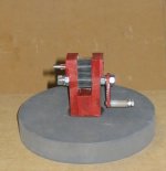
I finally decided to make a propper ribbon pleater. It's nothing fancy and actually a pretty close copy of one I've seen on the web. The only thing of real interest is that I found a source of cheap gears that will work for ribbons up to about 1/2 inches or maybe a little more. They cost all of 25 cents (!) each from BG Micro:
http://www.bgmicro.com/prodinfo.asp...S1155&page=1&cri=gears&stype=3&time_out=44:57
http://www.bgmicro.com/prodinfo.asp...S1155&page=1&cri=gears&stype=3&time_out=44:57
Attachments
More details - long
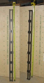
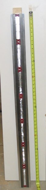
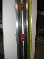
I did not have time last night to do much except post the pictures. Here are more details:
I have not listened to them yet. I still have to re-arrange my test setup as it does not lend itself to testing a four foot tall tweeter. It may take me a day or two to get everything re-arranged and rewired.
I spent this weekend dealing with two basic forces of nature: neodymium magnets and super glue") . I decided to attach all the magnets to each vertical pole piece and then connect the pole pieces with the crossbars. I stuck with super glue for the magnets - it's very nice to get an immediate bond. I worked out a process that allowed me to get the magnets placed correctly before the super glue caught. Towards the end it was working pretty smoothly.
. I decided to attach all the magnets to each vertical pole piece and then connect the pole pieces with the crossbars. I stuck with super glue for the magnets - it's very nice to get an immediate bond. I worked out a process that allowed me to get the magnets placed correctly before the super glue caught. Towards the end it was working pretty smoothly.
The neodymium magnets I'm using are VERY strong and I can't imagine trying to handle something much bigger. It took some real concentration to manhandle those things to go exactly where I wanted them. It also was a very good workout of my fingers. Once I had all the magnets on one pole (21 magnets) I felt like I was holding a loaded gun.
In order to position the two poles, without getting them stuck to each other, I taped a strip of half inch Styrofoam insulation to the magnets of one pole. Then I clamped that pole to the workbench. I then put a couple more temporary spacers in front of that pole before bringing the second pole piece over. The attraction between the two even at a distance of 1 1/2 inches was tremendous. They were pressing so hard against the spacers that it was very hard to rip away the two temporary pieces. Once I had the two pole pieces separated by just the single thickness of 1/2 inch insulation it was literally impossible for me to pull the poles apart.
One last interesting indication of the power was when I started attaching the cross pieces. The crosspieces were pulled out of my hand at about 2 inches and stuck to the steel poles. It was then impossible for me to separate them or even MOVE them with my hands. I had to use a rubber mallet and hit the cross piece hard to move it into position for the screws.
Once the magnets, poles, and crosspieces were assembled, the completed magnetic path made the assembly quite benign to handle, as long as you kept anything steel away from the gap. I HAVE to get some (non-magnetic) stainless steel screw drivers and 4-40 screws that I use to hold the ribbon ends. Several times I had the screwdriver pulled into the gap, ruining a just installed ribbon . I also had the 4-40 machine screws jump out of my hand and lodge in the gap, where it was again impossible for me to pull them out by hand. I had to use pliers, which also were attracted to the magnets. Like I said, I've got to get some non-magnetic stuff.
Regarding transformers; BG Micro also has a good price ($2.00) on what I expect to be excellent toroids for the matching transformers:
http://www.bgmicro.com/prodinfo.asp...1068&page=1&cri=toroid&stype=3&time_out=44:50
It has a little bigger cross section than the ones I used on the prototype. It is made of type "J" ferrite which appears to be better than the type "77" in my prototype toroids. The BH curve of the "J" is more linear than the "77" (the 77 has an odd wiggle that I have not seen on any other ferrite). Also, the two parts of the curve (backwards and forwards) are much closer and quite linear. I think this will reduce core losses and distortion.
I've wound these cores with several different winding arrangements to minimize leakage inductance. I ended up with a primary consisting of three series (per my previous post) multifilar windings of 17 turns each, using 18 AWG wire. This is the equivalent of a single 51 turn primary. For the secondary I used twelve parallel windings of # 24 AWG with nine turns. This gives it roughly the current carrying capacity of 13 AWG. My previous post about parallel secondaries not helping much is wrong - they help a LOT. The parallel secondary windings cut the leakage inductuctance by a factor of 2 or more over a single secondary. The combination primary and secondary multifilar windings I used ended up with a leakage inductance of .09 mh, measured with the inductance range of my multi-meter. Using a single 57 turn primary and a single 9 turn secondary gave me a leakage inductance of 1 mh. This is an excellent reduction.
Note that my multimeter uses a fixed frequency to measure - probably something like 1k. The leakage inductance is effectively in series with the primary so I am concerned about its value at 20k. I did a simple test of putting a four ohm resistor in series with the primary while I had the secondary tied together (this is how you measure leakage). I then ran 20 khz through the pair and found (by ratio of voltage drop) that the XL of leakage inductance at 20k is ~.8 ohms. This works out to .0064mh at 20k (if my math is right). This is quite good and means the high frequency cut due to leakage inductance (assuming an equivalent 8 ohm primary load) is much ess than 1 db.
This post went on longer than I expected. I'm not sure how many of you will make it to this sentence :rolleyes
I did not have time last night to do much except post the pictures. Here are more details:
I have not listened to them yet. I still have to re-arrange my test setup as it does not lend itself to testing a four foot tall tweeter. It may take me a day or two to get everything re-arranged and rewired.
I spent this weekend dealing with two basic forces of nature: neodymium magnets and super glue
. I decided to attach all the magnets to each vertical pole piece and then connect the pole pieces with the crossbars. I stuck with super glue for the magnets - it's very nice to get an immediate bond. I worked out a process that allowed me to get the magnets placed correctly before the super glue caught. Towards the end it was working pretty smoothly.The neodymium magnets I'm using are VERY strong and I can't imagine trying to handle something much bigger. It took some real concentration to manhandle those things to go exactly where I wanted them. It also was a very good workout of my fingers. Once I had all the magnets on one pole (21 magnets) I felt like I was holding a loaded gun.
In order to position the two poles, without getting them stuck to each other, I taped a strip of half inch Styrofoam insulation to the magnets of one pole. Then I clamped that pole to the workbench. I then put a couple more temporary spacers in front of that pole before bringing the second pole piece over. The attraction between the two even at a distance of 1 1/2 inches was tremendous. They were pressing so hard against the spacers that it was very hard to rip away the two temporary pieces. Once I had the two pole pieces separated by just the single thickness of 1/2 inch insulation it was literally impossible for me to pull the poles apart.
One last interesting indication of the power was when I started attaching the cross pieces. The crosspieces were pulled out of my hand at about 2 inches and stuck to the steel poles. It was then impossible for me to separate them or even MOVE them with my hands. I had to use a rubber mallet and hit the cross piece hard to move it into position for the screws.
Once the magnets, poles, and crosspieces were assembled, the completed magnetic path made the assembly quite benign to handle, as long as you kept anything steel away from the gap. I HAVE to get some (non-magnetic) stainless steel screw drivers and 4-40 screws that I use to hold the ribbon ends. Several times I had the screwdriver pulled into the gap, ruining a just installed ribbon
. I also had the 4-40 machine screws jump out of my hand and lodge in the gap, where it was again impossible for me to pull them out by hand. I had to use pliers, which also were attracted to the magnets. Like I said, I've got to get some non-magnetic stuff.Regarding transformers; BG Micro also has a good price ($2.00) on what I expect to be excellent toroids for the matching transformers:
http://www.bgmicro.com/prodinfo.asp...1068&page=1&cri=toroid&stype=3&time_out=44:50
It has a little bigger cross section than the ones I used on the prototype. It is made of type "J" ferrite which appears to be better than the type "77" in my prototype toroids. The BH curve of the "J" is more linear than the "77" (the 77 has an odd wiggle that I have not seen on any other ferrite). Also, the two parts of the curve (backwards and forwards) are much closer and quite linear. I think this will reduce core losses and distortion.
I've wound these cores with several different winding arrangements to minimize leakage inductance. I ended up with a primary consisting of three series (per my previous post) multifilar windings of 17 turns each, using 18 AWG wire. This is the equivalent of a single 51 turn primary. For the secondary I used twelve parallel windings of # 24 AWG with nine turns. This gives it roughly the current carrying capacity of 13 AWG. My previous post about parallel secondaries not helping much is wrong - they help a LOT. The parallel secondary windings cut the leakage inductuctance by a factor of 2 or more over a single secondary. The combination primary and secondary multifilar windings I used ended up with a leakage inductance of .09 mh, measured with the inductance range of my multi-meter. Using a single 57 turn primary and a single 9 turn secondary gave me a leakage inductance of 1 mh. This is an excellent reduction.
Note that my multimeter uses a fixed frequency to measure - probably something like 1k. The leakage inductance is effectively in series with the primary so I am concerned about its value at 20k. I did a simple test of putting a four ohm resistor in series with the primary while I had the secondary tied together (this is how you measure leakage). I then ran 20 khz through the pair and found (by ratio of voltage drop) that the XL of leakage inductance at 20k is ~.8 ohms. This works out to .0064mh at 20k (if my math is right). This is quite good and means the high frequency cut due to leakage inductance (assuming an equivalent 8 ohm primary load) is much ess than 1 db.
This post went on longer than I expected. I'm not sure how many of you will make it to this sentence :rolleyes
GREAT work, I can`t get enough of this......
This is one thrilling, stunning thread!
I read every single of Your words at least once or twice!
I`m very eager to hear about Your first listening impressions.
This post went on longer than I expected. I'm not sure how many of you will make it to this sentence :rolleyes
Lots of lookers. Not many talkers. Interested? Not-interested? Speechless? Bored?
This is one thrilling, stunning thread!
I read every single of Your words at least once or twice!
I`m very eager to hear about Your first listening impressions.
Member
Joined 2003
Yes, your work is appreciated
I've been (slowly) working on ribbons for about six months, so I am painfully aware of the bloody fingers and everything else you are going through!
1" ribbon protos
I've been (slowly) working on ribbons for about six months, so I am painfully aware of the bloody fingers and everything else you are going through!
1" ribbon protos
Sorry for the blatant appeal for comments.It was a tough day at work today and sometimes you need some responses. Thanks for the input. Onward and upwards!
Denis
BTW:
I did cut my fingers this weekend and even managed to slice off the tip of one finger! Everything is OK and Blue Cross -Blue Shield was not involved.
Denis
BTW:
I did cut my fingers this weekend and even managed to slice off the tip of one finger! Everything is OK and Blue Cross -Blue Shield was not involved.
Hi Denis,
Your continuing efforts look wonderful. There are many of us that are doing similar things that are very interested inyour progress. It's just that I for instance don't login every day. Sometimes not for several days at a time.
I am very interested to know what your ribbons sound like. Very much. Now that you're so close to powering them up I'll check in more often.
Why did you break the ribbon up into discreet sections instead of using one long piece of Al with a simple support where you now have the screa down anchor points? Do you have a transformer on each segment or are the segments connected in series with one transformer for the whole chain?
Nelson Pass is about to publish an article that is promising to include data on driving ribbon speakers with transconductance amplifiers. According to NP it goes up on www.passddiy.com today or within the next few days.
Keep up the great work. It's an inspiration. Truly.
Regards,
Graeme
- Status
- This old topic is closed. If you want to reopen this topic, contact a moderator using the "Report Post" button.
- Home
- Loudspeakers
- Planars & Exotics
- Another DIY Ribbon thread