Hi, jer
It's a VST plugin and you can read all about it/order here:
Electro-Music.com
You can also read about the basic ambiophonic playback method here:
Home Page
Ambiophonics is an improvement over conventional stereo -- it is worthwhile with almost all recordings and a BIG DEAL with really well recorded music.
Here is the link of the paper referred to earlier in this thread,
AES E-Library: Wide-Range Electrostatic Loudspeaker with a Zero-Free Polar Response
Wide-Range Electrostatic Loudspeaker with a Zero-Free Polar Response
AES E-Library: Wide-Range Electrostatic Loudspeaker with a Zero-Free Polar Response
Wide-Range Electrostatic Loudspeaker with a Zero-Free Polar Response
Yes, please.I have a hardcopy at home, but making it available here is probably not okay (IANAL). What I can do is paraphrase the gist of it, will do that later today if anyone is interested.
Kenneth
Some guidance like number/width of sections, RC time constants, suitable resistors (HV?), achievable pattern, difference from QUAD LC transmission line solution would of been really nice to know.
Best regards,
Alex
In my youth there was a High End shop in my town and i often
had the opportunity to listen to several acclaimed speakers there
back in the 80's.
Among those were these models from Harold Beveridge.
It was the speaker which left me with the deepest impression
of "correctness" and stability in imaging. It also had good dynamics
and an outstanding Bass reproduction (large Subwoofer ontop
of the ton shaped enclosure).
Detail resolution was very good, low coloration.
Maybe the uppermost top end was missing a bit, but
i do not remember exactly.
An ESL 63 from Quad e.g. was a decent speaker too,
there were also Magneplanars, several Lowther horns,
but compared to that Beveridge model from my memory
most of those speakers were degraded to be toys.
It was one of the experiences, which showed what is possible
with a consequent design.
I guess the world has turned since then and there may be further
speakers which are on a high level, but if you have the
opportunity you should give the beveridge models a listen.
Attachments

That's me poking you.Alex,
ok, I'll see if I can get this done over the weekend. Poke me if I don't answer by tuesday.
Kenneth
")
Sincerely,
Alex
Hi, real life got a little bit in the way. Here's a quick summary I made of the paper, let me know if something is unclear, then I'll try to elaborate!
Kenneth
* Walker's equation for on-axis SPL is linear with the signal current and has a 1/sqrt(f) dependency
* To use voltage drive and get a flat frequency response, we therefore need an impedance which is inverse proportional to the square root of the frequency. An RC transmission line satisfies this requirement.
* Since we use a finite number of sections, there are 3 operating areas:
1. Low frequencies: unattenuated by the transmission line, whole surface area used. Here the impedance becomes capacitive (1/f), and SPL becomes proport. to sqrt(f) so it rolls off at 10dB/decade.
2. Mid frequencies: desired flat response.
3. High frequencies: only the first RC section is active, the impedance is predominantly resistive and we get SPL proport. to 1/sqrt(f) so it rolls off at 10dB/decade.
* If N is the number of RC sections:
- the LF transition frequency is 1/(2 Pi N^2 RC)
- the HF transition frequency is 2/(Pi RC)
- the number of sections needed to have flat behavior from fL to fH is given by fH/fL = 4N^2
* For a good zero-free polar response, the segments should be no more than 10-12mm wide. This was determined by simulation. Hence, for a full-range ESL, 30 or more sections may be needed.
* Asymmetric ESL (RC line driven from one side of the speaker) has a very poor feature: the location of the peak in the polar response is a little off-axis and this is dependent on the frequency. Symmetric ESLs are much better: they obviously don't have this error. Also, the author shows that they have an inherent Butterworth (optimally flat) 2nd-order low-pass response in their polar response, giving a better sweet spot and very linear response near on-axis. Of course, symmetric construction doubles the number of sections in practice.
* With a segment width of w, a flat and linear polar response is obtained up to this frequency: (2RC c^2)/(Pi w^2) with c=speed of sound in air
* Terminating the transmission line with its Zc helps in reducing a "bump" in the response near fL but at the cost of a slightly higher fL. It is better to terminate the line with an impedance simulating between 0.1N and 0.15N additional segments.
Last edited:
Kenneth,
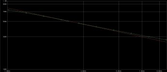
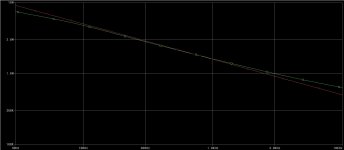
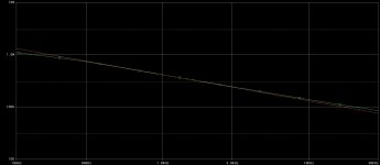
if it's all impedance wise 20 sections per panel half is relatively good.
Below are calculated plots magnitude of impedance vs frequency @ 20,40,80 sections.
It really unfortunate that the resistance per cell has to be quite high at low ladder length.
Alex
if it's all impedance wise 20 sections per panel half is relatively good.
Below are calculated plots magnitude of impedance vs frequency @ 20,40,80 sections.
It really unfortunate that the resistance per cell has to be quite high at low ladder length.
Alex
Attachments
Last edited:
Kenneth,
Thanks for the very useful contribution to this (old) thread. I've only done quick calculations based on bits and pieces of your summary because I don't have capacitance values to work with yet. If I start with this:
I find that a hybrid ESL running the ES portion from 300 Hz to 20 KHz only needs 4 sections for a flat response through the pass band. If the sections are to be kept no wider than 12 mm, as stated here:
I end up with unrealistically narrow panels (4 x 12 mm = 48 mm). Is this just meant to imply that while four sections are the minimum needed for flat response from 300 to 20000 Hz, many more sections are needed if you want to span that range with zero-free polar response and reasonable sound levels? Or am I simply missing something?
Few
Thanks for the very useful contribution to this (old) thread. I've only done quick calculations based on bits and pieces of your summary because I don't have capacitance values to work with yet. If I start with this:
the number of sections needed to have flat behavior from fL to fH is given by fH/fL = 4N^2
I find that a hybrid ESL running the ES portion from 300 Hz to 20 KHz only needs 4 sections for a flat response through the pass band. If the sections are to be kept no wider than 12 mm, as stated here:
For a good zero-free polar response, the segments should be no more than 10-12mm wide.
I end up with unrealistically narrow panels (4 x 12 mm = 48 mm). Is this just meant to imply that while four sections are the minimum needed for flat response from 300 to 20000 Hz, many more sections are needed if you want to span that range with zero-free polar response and reasonable sound levels? Or am I simply missing something?
Few
Hi,
That seems to agree with the paper: indeed 4*4^2 ~= 20000/300
One important remark: nothing keeps you from using more sections if you end up with undesired results. If you use more sections than necessary, you can get whatever ESL width you want and also make the sections even smaller than 12mm, improving the polar response at high frequencies even further.
The 'ideal' sectioning would be an infinite number of infinitely narrow sections Think stators with a resistive coating, fed from a central strip
To continue with your example: in an asymmetrical ESL with 4 sections, yes (according to this paper) you would end up with 48mm max if you want a zero-free polar response. Whether or not such an ESL could generate sound down to 300Hz is an additional requirement which needs to be checked on a case-to-case basis. Personally I think it is very possible to make such an ESL.
If the ESL is made symmetrical (recommended), we get 7 sections (center-fed) and a width of 84mm.
Other important remark: the paper discusses the low frequency -3dB point fL due to sectioning, but in practice you'll have another fL due to dipole baffle step (front-back cancellation). The former is determined by the number of sections, and the fact that the RC transmission line no longer acts like a transmission line below that frequency. The latter is determined by the width of the speaker which is quite unrelated from N. Then there is a third unrelated effect that the SPL output drops down below the membrane's mechanical resonance frequency. Whew!
HTH
Kenneth
I find that a hybrid ESL running the ES portion from 300 Hz to 20 KHz only needs 4 sections for a flat response through the pass band.
That seems to agree with the paper: indeed 4*4^2 ~= 20000/300
If the sections are to be kept no wider than 12 mm, as stated here: [...] I end up with unrealistically narrow panels (4 x 12 mm = 48 mm). Is this just meant to imply that while four sections are the minimum needed for flat response from 300 to 20000 Hz, many more sections are needed if you want to span that range with zero-free polar response and reasonable sound levels? Or am I simply missing something?
One important remark: nothing keeps you from using more sections if you end up with undesired results. If you use more sections than necessary, you can get whatever ESL width you want and also make the sections even smaller than 12mm, improving the polar response at high frequencies even further.
The 'ideal' sectioning would be an infinite number of infinitely narrow sections
Think stators with a resistive coating, fed from a central strip To continue with your example: in an asymmetrical ESL with 4 sections, yes (according to this paper) you would end up with 48mm max if you want a zero-free polar response. Whether or not such an ESL could generate sound down to 300Hz is an additional requirement which needs to be checked on a case-to-case basis. Personally I think it is very possible to make such an ESL.
If the ESL is made symmetrical (recommended), we get 7 sections (center-fed) and a width of 84mm.
Other important remark: the paper discusses the low frequency -3dB point fL due to sectioning, but in practice you'll have another fL due to dipole baffle step (front-back cancellation). The former is determined by the number of sections, and the fact that the RC transmission line no longer acts like a transmission line below that frequency. The latter is determined by the width of the speaker which is quite unrelated from N. Then there is a third unrelated effect that the SPL output drops down below the membrane's mechanical resonance frequency. Whew!
HTH
Kenneth
Last edited:
Other important remark: the paper discusses the low frequency -3dB point fL due to sectioning, but in practice you'll have another fL due to dipole baffle step (front-back cancellation). The former is determined by the number of sections, and the fact that the RC transmission line no longer acts like a transmission line below that frequency. The latter is determined by the width of the speaker which is quite unrelated from N. Then there is a third unrelated effect that the SPL output drops down below the membrane's mechanical resonance frequency.
Kenneth
Hello kavermei,
As you pointed out, the effect of diaphragm resonance on the response is not considered by the paper. Neither is the matter of HF resonance between leakage inductance and panel capacitance which is a dominate factor in defining the HF roll-off behavior. The matter of capacitive coupling between segments is also ignored. In practice more high frequency energy couples to the outer sections than the theory assumes, bypassing the transmission line resistors.
However, the dipole roll-off behavior of a line source is contained in the line-source version of the Walker equation. For floor to ceiling line sources, the native response falls -3dB per octave with decreasing frequency. You do not have to account for it separately
1) If your line source is not fully floor to ceiling, you will get an additional -3dB roll-off below the frequency where the height of the line source is half wavelength. Thus -6dB/octave decreasing below this breakpoint frequency. See the AES paper "The Acoustic Radiation of Line Sources of Finite Length" by Lipshitz & Vanderkooy for more details.
2) If you add baffle wings to the sides of the a line source ESL panel you will halt the -3dB roll-off slope from frequency f1 where half wavelength equals the width of the ESL panel until the f2 where half wavelength equals the width of the (ESL panel + baffle). Below f2 response reverts back to the -3dB/octave slope.
Thanks for sharing such an important info.
I am still confused...
What are we trying to obtain?
1. 1/Sqrt(f) to equalize the response?
According to simulations 4 sections are not even near
2. Time delay to enhance off axis response (eliminate beaming)?
Walker defines the purpose as a formation of a particular wavefront driving concentric rings through the dealy line.
Then the ratio of phase/frequency have to rize propotionally to the frequency applied. Again by simulation 4 sections have decent accuracy for 1 decade, let's say 200Hz-2000Hz
3. Time dealy of the line does not depends on frequency. Or is it?
Let's assume we applied step to the input (central strip). This step will appear on each tap (more or less distorted) with the dealy depending on propagation speed of a given line.
I have to read the original - that's my verdict.
Thanks,
Alex
P.S. It's definetely a grey area:
http://en.wikipedia.org/wiki/Phased_array_ultrasonics
http://www.explorelearning.com/index.cfm?method=cResource.dspDetail&ResourceID=37
Attachments
Last edited:
I find that a hybrid ESL running the ES portion from 300 Hz to 20 KHz only needs 4 sections for a flat response through the pass band. If the sections are to be kept no wider than 12 mm...I end up with unrealistically narrow panels (4 x 12 mm = 48 mm). Is this just meant to imply that while four sections are the minimum needed for flat response from 300 to 20000 Hz, many more sections are needed if you want to span that range with zero-free polar response and reasonable sound levels? Or am I simply missing something?
I think kavermei already addressed this question, but I thought I'd add a few comments. Yes, 4 sections is all that is needed to achieve flat on-axis response from 300hz - 20kHz. But, like you said, if you want to use a minimum section width of 1/2" and only 4 sections, you won't have much panel area, so your ESL won't be very loud.
When designing a panel, I'd suggest starting out by:
1) defining the largest panel(height & width) you can live with. This will give you the highest sensitivity and maxSPL.
2) Then, pick your LF breakpoint. With area already defined in 1), this also sets the max SPL for your design.
3) Figure how many sections you need to reach beyond 20kHz.
4) If your sections are already 1/2" or whatever you deem "small enough" then you are done. Otherwise, increase the number of sections until you get there. Your high frequency extension will be much higher then needed, but the leakage inductance of your transformer will most likely cut of the HF response at not much higher than 20kHz.
Another option is to only use the "small enough" section width on the first few sections of the transmission line and then increase the size of the section after that. If you look at the frequencies fed to each section you can see that as you travel down the line you pretty quickly lose the highs that would cause beaming problems. You just need to adjust the size of the transmission line resistors when you reach these sections.
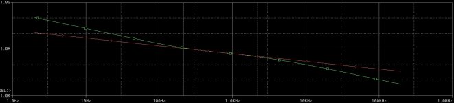
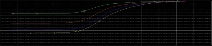
I had thrown together an XL spreadsheet a few months back to allow fiddling with panel size, LF breakpoint, and number of sections to see how they affected efficiency and max SPL. It also calculated sections sizes, capacitance, and feed resistor sizes. Unfortunately looks I left it at work. I do have a screenshot I'd saved at one time shown here so you can get an idea what I am talking about.
Inputs 1 thru 4 define panel size and listening distance. This defines the max obtainable SPL for the line source seen in blue on the plot. Note the 3dB/octave slope as defined by the line-source version of the Walker Equation.
Inputs 5 & 6 define the LF breakpoint and number of sections. The resulting response is shown in red on the plot.
I'll be back to work on Tuesday, and should be able to post the spreadsheet for you to experiment with then.
Attachments
Hi,
I'll have to look that one up, the variation used in the paper only contains height (h), distance to the listener (r), and D/S spacing (d):
P = I(signal) * V(pol) / (2 Pi d h sqrt(c r f) )
Couldn't agree more, but an often forgotten condition for line source behavior is having good reflection on floor and ceiling. Too much carpet and even a floor-to-ceiling ESL will not be a purely cylindrical source at higher frequencies...
Kenneth
However, the dipole roll-off behavior of a line source is contained in the line-source version of the Walker equation. For floor to ceiling line sources, the native response falls -3dB per octave with decreasing frequency. You do not have to account for it separately
I'll have to look that one up, the variation used in the paper only contains height (h), distance to the listener (r), and D/S spacing (d):
P = I(signal) * V(pol) / (2 Pi d h sqrt(c r f) )
1) If your line source is not fully floor to ceiling, you will get an additional -3dB roll-off below the frequency where the height of the line source is half wavelength. Thus -6dB/octave decreasing below this breakpoint frequency. See the AES paper "The Acoustic Radiation of Line Sources of Finite Length" by Lipshitz & Vanderkooy for more details.
Couldn't agree more, but an often forgotten condition for line source behavior is having good reflection on floor and ceiling. Too much carpet and even a floor-to-ceiling ESL will not be a purely cylindrical source at higher frequencies...
Kenneth
I am still confused...
What are we trying to obtain?
1. 1/Sqrt(f) to equalize the response?
Yes
2. Time delay to enhance off axis response (eliminate beaming)?
Walker defines the purpose as a formation of a particular wavefront driving concentric rings through the dealy line.
IIUC, the purpose is to minimize the delay because too much delay causes zeros to appear in the polar response at higher frequencies. The aim in this paper is not a point source like the QUAD 63, but a line source, so requires no deliberate delay.
The paper contains a formula for polar response based on 3 effects:
1. cos(theta) off-axis attenuation because of dipole
2. sinc(A f sin(theta) ) attenuation (A is a constant) because output from different segments arrives out-of-phase at the off-axis listener position
3. complicated factor containing sin(theta)^(-2) because the output of different segments has different time delay due to the RC line.
Kenneth
- Status
- This old topic is closed. If you want to reopen this topic, contact a moderator using the "Report Post" button.
- Home
- Loudspeakers
- Planars & Exotics
- experiences with ESL directivity?