It is the recently no-longer-supported MS Office 2011 (and good chance some of us will not want any MS upgrades hereafter). I get some buggy messages from MS. Shoddy products, not up to Apple standards esp user experience....As much as I like to complain about Microsoft and Apple software, I believe that error is due to uninstalled service packs. The spreadsheet may work just fine even with the error...can't tell you for sure though. If you let me what version of Excel you are running, I can email you a copy saved for that version that should open up fine.
Unlikely to have missing service upgrades.
No plans presently for me to use your generously provided app. Just helping fellow Apple fanboys know that Numbers will boot it. Pity about other sims.
B.
Attachments
I received by email an alert that a thread of interest had a new post. I read it and thought “Yes, that really is right down my alley.” It took me a bit to realize the thread was familiar but ~14 years old. That’s quite a run! Thanks, Bolserst, for such useful updates!
Few
Few
Regarding the use of ESL_line_sectioned_DIY_v4 and esl_seg_ui: more the sections more the high frequencies with the asymmetric configuration 1?
In my case the wires are only 42 so getting double the central section is impossible....
with 9 (8 + 1) sections I set the nearest value that is: 10 4 4 4 4 or, with 11 sections 12 3 3 3 3 3.
another thing i noticed that if i increase the value of the resistors suggested by ESL_line_sectioned_DIY_v4 the results in esl_seg_ui improve, why?
… i noticed that if i increase the value of the resistors suggested by ESL_line_sectioned_DIY_v4 the results in esl_seg_ui improve, why?
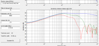
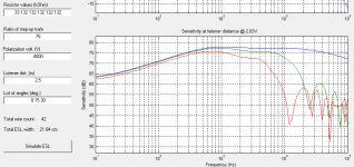
There is an interdependence of HF(high frequency) dispersion, SPL, and fL(low frequency break point) or bass extension.
As one would expect with mother nature, there are trade-offs in desirable characteristics.
Increase segmentation resistors: SPL is reduced
 , fL is reduced
 , HF dispersion is increased or improved
Decrease segmentation resistors: SPL is increased
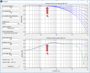
, fL is increased, HF dispersion is decreased or worsenedThat attached set of plots shows response for fL = 100, 200, and 400Hz, by doubling segmentation resistor values.
You can see the trend in fL, SPL, and HF dispersion.
Attachments
A version of the spreadsheet saved in post Excel 2007 format was sent and solved the import errors.It is the recently no-longer-supported MS Office 2011...
Thanks to bentoronto for reporting back results. If anybody else is having similar issues, let me know.
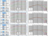
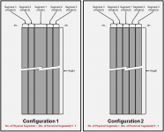
Have had a few PM on the topic of trade-offs in HF dispersion when trying to decide on number of segments and whether to use symmetric Configuration 1 or 2.
- If your panel width and fL have been chosen, the dispersion will improve with increasing number of segments up to a point.
Beyond that, further increase in number of segments does not improve the dispersion further for frequencies < 20kHz. - Configuration 2 needs only half the number of segments as Configuration 1 to achieve nearly the same HF dispersion.
- Be sure to consider the output impedance of your amplifier when deciding which Configuration to use. In particular, it is not unusual for tube amplifiers to have output impedances of several ohms which will cause HF response to droop with Configuration 2 because it requires much lower series resistance feeding the central segment.
Thanks to alexIG for identifying this issue.
Post with plots comparing polar response for different number of segments and configuration:
Thinking about a segmented wire stator ESL #39
Further posts on these topics:
Thinking about a segmented wire stator ESL #23
Thinking about a segmented wire stator ESL #79
Attachments
Newbie Questions
Please excuse my novice questions, but I would like to get some confirmations on the proper use of the Excel model.
I am modeling a push/pull, 2-stator design. How is the 2-stator versus 1-stator input data differentiated in the spreadsheet ? Are the data input fields in the "ESLline(SPL calc)" worksheet intended to be for a single stator or does something have to be done to represent 2 stators ?
I calculated the center to center wire (C2C_DISTANCE) distance, multiplied it by the total number of wires and entered it into "2 ==>", cell C10 as =(TOTAL_NUMBER_OF_WIRES * C2C_DISTANCE). Is this the intended width for this field, or is it something else (e.g. mylar width) ?
The design is 7 + 1 + 7 = 15 segments. I entered 15 into "5==>", "# electrical segments", cell C18, is that correct or should it be 7, 8 or something else ?
The formula's resulting value in w(sec), cell C24, "width section" matches the value I calculated which seems to confirm the preceding.
Each electrical section has 6 wires in a single coil (if I am using the proper terminology) on each stator. When I enter 6 in "13 ==>", "# wires per section", cell C41, it generates the following on the "System Config(2)" worksheet, "3 3 3 3 3 3 3 3 3 3 3 3 3 3", 14 3's. Is this correct ? I was assuming it would be 6 something as entered on the "ESLline (SPL calc)" worksheet.
The "distance between wire center (mm)" on the "System Config(2)" worksheet matches what I calculated.
I haven't tried using the esl_seg_ui yet until I understand the spreadsheet.
Thank you for your help and again, excuse the newbie questions.
Here is Version 4 of the spreadsheet. ...
- ...
- Added input to specify number of wires per section to use for the esl_seg_ui import data.
...
Let me know if you have any questions or if something doesn’t seem to be working properly.
Please excuse my novice questions, but I would like to get some confirmations on the proper use of the Excel model.
I am modeling a push/pull, 2-stator design. How is the 2-stator versus 1-stator input data differentiated in the spreadsheet ? Are the data input fields in the "ESLline(SPL calc)" worksheet intended to be for a single stator or does something have to be done to represent 2 stators ?
I calculated the center to center wire (C2C_DISTANCE) distance, multiplied it by the total number of wires and entered it into "2 ==>", cell C10 as =(TOTAL_NUMBER_OF_WIRES * C2C_DISTANCE). Is this the intended width for this field, or is it something else (e.g. mylar width) ?
The design is 7 + 1 + 7 = 15 segments. I entered 15 into "5==>", "# electrical segments", cell C18, is that correct or should it be 7, 8 or something else ?
The formula's resulting value in w(sec), cell C24, "width section" matches the value I calculated which seems to confirm the preceding.
Each electrical section has 6 wires in a single coil (if I am using the proper terminology) on each stator. When I enter 6 in "13 ==>", "# wires per section", cell C41, it generates the following on the "System Config(2)" worksheet, "3 3 3 3 3 3 3 3 3 3 3 3 3 3", 14 3's. Is this correct ? I was assuming it would be 6 something as entered on the "ESLline (SPL calc)" worksheet.
The "distance between wire center (mm)" on the "System Config(2)" worksheet matches what I calculated.
I haven't tried using the esl_seg_ui yet until I understand the spreadsheet.
Thank you for your help and again, excuse the newbie questions.
Last edited:
The spreadsheet and els_seg_ui assume the traditional 2 stator configuration.…Are the data input fields in the "ESLline(SPL calc)" worksheet intended to be for a single stator or does something have to be done to represent 2 stators ?
Input 2==> defines the total “driven” width of the ESL based on Asymmetric or Symmetric Config (1) geometry. If you are using one of those configurations, you can simply measure the width of the stators or calculate based on total number of wires and C2C distance. If you plan to use Symmetric Config (2) the width needs to be adjusted slightly to be the (total number of electrical sections) *( width of outer electrical sections).I calculated the center to center wire (C2C_DISTANCE) distance, multiplied it by the total number of wires and entered it into "2 ==>", cell C10 as =(TOTAL_NUMBER_OF_WIRES * C2C_DISTANCE). Is this the intended width for this field, or is it something else (e.g. mylar width) ?
Think of an electrical segment as a group of wires that receives the same electrical signal. For Symmetric configurations, these electrical segments are split in half and each physical half placed symmetrically about the central segment. The symmetric configuration TABs contain images that help to clarify the relationship between physical segments and electrical segments. You may have to scroll down to seem them. The image for Symmetric Config (2) is attached.The design is 7 + 1 + 7 = 15 segments. I entered 15 into "5==>", "# electrical segments", cell C18, is that correct or should it be 7, 8 or something else ? The formula's resulting value in w(sec), cell C24, "width section" matches the value I calculated which seems to confirm the preceding.
If you have 7 + 1 + 7 sections of 6 wires, this would be a Symmetric Config (2) with 8 electrical sections; the central electrical section has 6 wires, the outer 7 electrical sections have 12 wires(6 on left + 6 on right). The width you would put in 2==> would be 8 * 12 * C2C. The calculated w(sec) value is the width of the electrical section(ie 12 wires)
In 13==> you enter the number wires in an electrical section. In your case, 12. The System Config(2) Tab should now specify “6 6 6 6 6 6 6 6” for the “wires per segment” input to esl_seg_i. In this esl_seg_ui input block, the first number specifies the number of wires for the center segment. Each successive number specifies the number of wires in each physical section arranged symmetrically about the central segment. So, a second number of “6” means section 2 is made up of 6 wires to the left of the central segment AND 6 wires to the right of the central segment. Total width = C2C*(N1 + 2*N2, + 2*N3 + …)When I enter 6 in "13 ==>", "# wires per section", cell C41, it generates the following on the "System Config(2)" worksheet, "3 3 3 3 3 3 3 3 3 3 3 3 3 3", 14 3's. Is this correct ? I was assuming it would be 6 something as entered on the "ESLline (SPL calc)" worksheet.
No worries, let me know if anything needs further clarification.Thank you for your help and again, excuse the newbie questions.
Attachments

Another question about Version 4 of the spreadsheet.
The spreadsheet lists the requisite resistor values for each segment for a given set of model characteristics.
Is there a way (formula) to determine at what low pass frequency each segment is being truncated at based on the resistor values ?
TIA
The spreadsheet lists the requisite resistor values for each segment for a given set of model characteristics.
Is there a way (formula) to determine at what low pass frequency each segment is being truncated at based on the resistor values ?
TIA
Last edited:
Experiences?
Hi everyone,
I have browsed this thread, but did not see (or overlooked) posts about actual experiences with the directivity of the frequency-shaded style of panel that the last page or so has been detailing as a DIY project.
Any measurements or listener reports?
cheers
Hi everyone,
I have browsed this thread, but did not see (or overlooked) posts about actual experiences with the directivity of the frequency-shaded style of panel that the last page or so has been detailing as a DIY project.
Any measurements or listener reports?
cheers
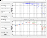
Probably the easiest way to visualize the progressive LP behavior as you move along the segments is to load the segment sizes and resistor values into the esl_seg_ui utility, and look at the upper plot which shows frequency response of the voltage across each segment. Example from Post#100 attached. You can see the response isn't “truncated", but rather gently rolled off. Are you interested in the -3dB down point? There is probably a way to calculate it, but I’m not sure how useful that information would be. What did you have in mind?…Is there a way (formula) to determine at what low pass frequency each segment is being truncated at based on the resistor values ?
Attachments
There have been a few detailed build threads over the years, but not many measurements that I recall.I have browsed this thread, but did not see (or overlooked) posts about actual experiences with the directivity of the frequency-shaded style of panel that the last page or so has been detailing as a DIY project. Any measurements or listener reports?
Here are a few links I had saved to get your started...
Polar measurements and comments on one of my segmented ESLs:
Glue for wire stators
First time ESL builder
Some off-axis measurements of a segmented ESL of this style at bottom of page:
Frequency measurements | Steen Frank Jensen
jamesthomas128’s build thread and listening comments:
First time ESL builder
CharlieM’s segmented ESL build thread and blog:
Yet another segmented ESL
http://jazzman-esl-page.blogspot.com/
golfnut’s segmented ESLs:
Another segmented ESL
keyboard123’s segmented ESLs:
An Segmented Hybrid ESL. In the footsteps of Jazzman.
Ken Seibert's web page:
http://kenseibert.com/esl/stators.asp
Probably the easiest way to visualize the progressive LP behavior as you move along the segments is to load the segment sizes and resistor values into the esl_seg_ui utility, and look at the upper plot which shows frequency response of the voltage across each segment. Example from Post#100 attached. You can see the response isn't “truncated", but rather gently rolled off. Are you interested in the -3dB down point? There is probably a way to calculate it, but I’m not sure how useful that information would be. What did you have in mind?
That's for the quick response and information. Truncate was the wrong term to use.
I knew it was a roll off, but didn't now how steep it was, nor how to determine how much of the panel was covering what frequencies (besides the center full range segment).
The information was more out of curiosity to see how different the various segmented panel designs are from a flat panel and how much high end was removed from the sides.
@bolserst @CharlieM
Hi all ESL lovers!
I'm slowly trying to figure out the version 4 calculator - with a view to symmetrical segmented stators. Largely I'm basing my design off of Charlies blog - but smaller 1200mm x 300mm (4'x1').
Have to confess, I'm a bit of an ignoramus with electrics - but fearful enough to usually remain safe!
I've got two questions at the moment.
1. How do I calculate my amplifier Vrms - presumably this is the voltage it outputs?
The amplifier has an input sensitivity of 0.775 Vrms. Amplifier is rated at 135 watts into 8 ohms.
2. How do I calculate the step-up ratio of the transformer(s). I've bought 4 transformers (similar to Charlie's suggestions) dual windings, 115 / 230 Vac to 2 x 6 Vac. Does that make the ration 115/6=19 ?
All help and pointers greatly appreciated
To estimate your amplifier Vrms output capability:
Vrms = sqrt(Watts*ohms) = sqrt(135*8) = 32.9 Vrms
This will of course change somewhat with what impedance the amplifier is driving.
I’d recommend using 30Vrms in the spreadsheet for design purposes.
If you are using your transformers the way Charlie does (2 per speaker with 6V windings in parallel and 230V windings in series) the step-up ratio will be roughly 2 *(230/6) = 76.7. This estimate will be on the high end. The VA rating and designed voltage regulation % will drop it some. I’d recommend using 70 in the spreadsheet for design purposes.
Many thanks for your help @bolserst
I ran the figures through the version 4 spreadsheet, but there seemed to be some issues with macro ranges (I'm running osx and libre office..)
Any how - I put the figures into the version 3 spreadsheet I dropped the LF cutoff down to around 150hz and R value came out the same as Charlie's! Taken the plunge and ordered some parts - basically the same as Charlies!
Presently listening to Osibisa on non-ESLs !!
- Status
- This old topic is closed. If you want to reopen this topic, contact a moderator using the "Report Post" button.
- Home
- Loudspeakers
- Planars & Exotics
- experiences with ESL directivity?