Hello Bolserst
I'm sorry that lowmass no longer posts. I hope he comes back.
Of course I had already read the posts you indicated to me, but rereading is always useful. I don't think that in the tests I did the airgap had much to do with it, as it was always quite high, at least 3 mm, and moreover I got similar results with ribbons with side suspension, where there is no airgap. Instead I am increasingly convinced that ribbon stiffness and damping are the primary causes of distortion, and I will be testing this in the future. Thanks for the links.
This ribbon looks like one with multiple traces ? if so, the current wont be that high in such a design. so iron or bare magnet wont change much if you ask me.
magnetic field (like an even field) by either using another arangement (like using 2 stacked magnets with the same polarity, gives a verry flat field in the middle of the gap) or changing up you straces (like wider near the magnet where the field is stronger to even out how it is driven) will change distortion, and maybe type of corugation in combination with what sort of foil is used. a foil with a mylar backing always did better then a solid alu foil in my contraptions. (except in effiiciency, maybe) the mylar and glue gives some damping. and solid foild tended to have a few resonances
also some distortion tends to come from the connection (some people suggested using vaseline to battle corosion), and some of the distortion came from where it is no longer supported (near the clamp) in my contraptions at least
Last edited:
Hi Wrinex
I still don't understand how partial quotes are handled, so I'll copy and paste
Quote: This ribbon looks like one with multiple traces ? if so, the current wont be that high in such a design. so iron or bare magnet wont change much if you ask me.
I agree with you, and this is the result of the measures I posted.
Yes, the ribbons of which I posted the measurements were all 4-track and the current was a maximum of a few Amps, but I also measured true ribbons (1 strip) with currents of about 15 A peak, with similar results. I wanted the experimental proof that not only the iron or the naked magnet make no difference, but that the modulation effect of the magnetic field, present in the moving coil loudspeakers, in the ribbons does not exist.
Quote: magnetic field (like an even field) by either using another arangement (like using 2 stacked magnets with the same polarity, gives a verry flat field in the middle of the gap) or changing up you straces (like wider near the magnet where the field is stronger to even out how it is driven) will change distortion, and maybe type of corugation in combination with what sort of foil is used. a foil with a mylar backing always did better then a solid alu foil in my contraptions. (except in effiiciency, maybe) the mylar and glue gives some damping. and solid foild tended to have a few resonances
Here, too, I fully agree with you. Up to now I have also used multitrack ribbons, only instead of mylar I use a very light paper backing which seems to me to give more damping. Every so often, however, I try with the single track and lately I have noticed some differences in the THD that I want to deepen.
You can be more specific about what you mean by "using 2 stacked magnets with the same polarity"?
Quote: also some distortion tends to come from the connection (some people suggested using vaseline to battle corosion), and some of the distortion came from where it is no longer supported (near the clamp) in my contraptions at least
I also happened to verify distortions coming from the contacts, so for some time I have been using chemical zinc plating on the ends, and I have not had any more trouble. If I understand correctly, have you noticed distortions coming also from the part of the tape after the contacts, that is, from the part that does not carry current? In my creations I have never noticed vibrations on those parts.
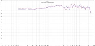
At the suggestion of esl 63 I made some measurements to see the difference between voltage driving and current driving. I remade the PCB of my test amplifier so that I can switch the feedback from voltage to current with a few solders. After verifying that everything was working well I made measurements on 2 different ribbons. Both are formed by 4 strips Alu 12 um thick, in series, held by 12 g / m ^ 2 paper, for a total width of 27 mm, with corrugations on a few cm at the ends, but while one (C21A) was finely embossed in the part immersed in the magnetic field, the other (C21B) had longitudinal ribs for stiffening.
I only report the measurements on the C21A ribbon, as the other were the same
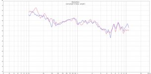
C21A_V & I_SPL
C21A_V&I_THD
They are the same, as expected, but the responses to transients are quite different. I didn't trust REW's calculated responses, and measured them with another microphone and oscilloscope.
C21A with voltage drive
C21A with current driving
C21B with voltage drive
C21B with current driving
The images need no comment.
At this point, at least for me, the current driving, with regard to HIFI, is dead and gone
I only report the measurements on the C21A ribbon, as the other were the same
C21A_V & I_SPL
C21A_V&I_THD
They are the same, as expected, but the responses to transients are quite different. I didn't trust REW's calculated responses, and measured them with another microphone and oscilloscope.
C21A with voltage drive
C21A with current driving
C21B with voltage drive
C21B with current driving
The images need no comment.
At this point, at least for me, the current driving, with regard to HIFI, is dead and gone
Attachments


what was the ampilifier used and how did you implement the swithcing between current drive and voltage drive?
I'm not against your POV, indeed it would be beneficial for my setup as I just finished developing a very low thd amp only capable of voltage drive. so I'm just curious...
I'm not against your POV, indeed it would be beneficial for my setup as I just finished developing a very low thd amp only capable of voltage drive. so I'm just curious...
Hi Tfive
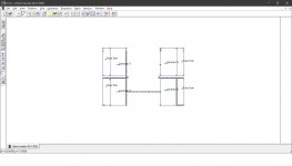
All Vin-Vout amplifiers have feedback. They take a portion of the Vout and send it to Vin for subtraction. To convert the Vin-Vout amplifier into a Vin-Iout amplifier, it is sufficient to take a portion of Iout for the feedback instead of a portion of Vout. While there are several ways to do this, I did it in the simplest way, putting a small R in series with the load (about 1/5_1/20 of the load) and taking the feedback from there. In the Vin-Iout case the load no longer has a GND end, but in most cases this does not create problems. For clarity, the schematics prepared for Vin-Iout has been placed. To switch to Vin-Vout just move the negative connection of the load from OUT-_I to OUT-_V and move the jumper between U$1 and U$2 and put it between U$6 and U$3. Of course, other solutions or variants are possible.
All Vin-Vout amplifiers have feedback. They take a portion of the Vout and send it to Vin for subtraction. To convert the Vin-Vout amplifier into a Vin-Iout amplifier, it is sufficient to take a portion of Iout for the feedback instead of a portion of Vout. While there are several ways to do this, I did it in the simplest way, putting a small R in series with the load (about 1/5_1/20 of the load) and taking the feedback from there. In the Vin-Iout case the load no longer has a GND end, but in most cases this does not create problems. For clarity, the schematics prepared for Vin-Iout has been placed. To switch to Vin-Vout just move the negative connection of the load from OUT-_I to OUT-_V and move the jumper between U$1 and U$2 and put it between U$6 and U$3. Of course, other solutions or variants are possible.
Attachments
I also happened to verify distortions coming from the contacts, so for some time I have been using chemical zinc plating on the ends, and I have not had any more trouble. If I understand correctly, have you noticed distortions coming also from the part of the tape after the contacts, that is, from the part that does not carry current? In my creations I have never noticed vibrations on those parts.
Ur my hero
since i was wondering about that for ages. and noone had the answer can you plate chemically alu?. to make decent connections. at the time i had no money and did not want to try it myself. since i collect so many crap that i never use again NICE i am buying some ! thats an awesome discovery!did you buy MG chemical ? or another brand, i want to be sure it also works for me.
you used zinc plating ? hmm so still not solder able though (but prevents corrosion ofc), any idea about https://nl.farnell.com/mg-chemicals/421-500ml/tin-plating-liquid-bottle-475ml/dp/2811902 tin plating ? that would be even more awesome.
what i ment by distortion from unsupported part. is like the transition to where it is clamped to where it is free to move. i think there should be added weight or supported by foam or felt from both sides. it tends to create distortion on the edge where it becomes (semie free to move, since its so close to a supported part it cant swing like in the midle of the ribbon)
Last edited:
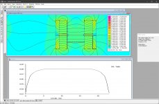
here is a femm model with the magnet arrangement.
its not strong but huge, but ignore the strength. just see how flat it is.
you can play wit the distance in between the magnets to get different results in this case it was 2 mm
its not strong but huge, but ignore the strength. just see how flat it is.
you can play wit the distance in between the magnets to get different results in this case it was 2 mm
Attachments
Ur my hero
did you buy MG chemical ? or another brand, i want to be sure it also works for me.
Hi Wrinex
For zinc plating I do not use ready-made baths because with what 100 cc of bath cost I can buy the components to make 2 liters. I was inspired by this video:
SHS - chemical nickel plating aluminium foil - YouTube
First they do the zinc plating and then the nickel plating, but I only do the first one because for the nickel plating you have to bring the bath to 90 ° C and it is a little complicated as well as emitting annoying vapors. But I tried once and that works too.
The galvanizing bath for me works well with these proportions, per liter of H2O:
18g/l of ZnO, + 120g/l of NaOH.
ZnO does not dissolve in the diluted solution, so you must first make a solution with all Na (OH) and a little water so that the solution is 40-50%, then dissolve all the ZnO in it, then dilute as required. If you still have difficulties, solve by heating the solution a little (one-two tens of seconds in the microwave for half a glass). Once the galvanizing bath has been prepared, you need to equip yourself with a cleaning bath (5-7% NaOH solution) and 2 rinsing baths, the first with tap water, the second with distilled water. After having lightly rubbed the end of the ribbon with acetone, immerse it for 10-15 seconds in the cleaning bath, then 10s in the first rinse, then 10s in the second rinse and finally 15-30s in the galvanizing bath, depending on the temperature. I have seen that it works best at 30-40 ° C.
It works well for me the first time, but it seems that normally (always and to everyone) the first deposit is not adherent. If so, wipe it off with a clean cloth (or paper) and repeat all dives. The second deposit is certainly adherent. To remove the first deposit they recommend nitric acid, but it works fine for me as I said.
Let me know if you run into any difficulties.
Ur my hero
you used zinc plating ? hmm so still not solder able though (but prevents corrosion ofc), any idea about https://nl.farnell.com/mg-chemicals/421-500ml/tin-plating-liquid-bottle-475ml/dp/2811902 tin plating ? that would be even more awesome.
Hi Wrinex
No, zinc plated on aluminum is not weldable, however it is still the first mandatory step for subsequent weldable depositions, such as nickel or better, for the tests I have done, copper. For tin plating, which can only be done on copper, some time ago I used a French product with the name etamag and it worked in the sense that it covered the copper with tin, but then to solder it was necessary to rub with the tip of the soldering iron until the deposited layer was removed. so I gave up and now I tin the PCBs with a soldering iron and plenty of flux. Moreover, etamag after a few years no longer worked at all. I don't know the product you linked, but I'm very skeptical.
here is a femm model with the magnet arrangement.
its not strong but huge, but ignore the strength. just see how flat it is.
you can play wit the distance in between the magnets to get different results in this case it was 2 mm
Thanks for the explanation, WrineX
Ur my hero
you used zinc plating ? hmm so still not solder able though (but prevents corrosion ofc), any idea about https://nl.farnell.com/mg-chemicals/421-500ml/tin-plating-liquid-bottle-475ml/dp/2811902 tin plating ? that would be even more awesome.
Hi Wrinex
No, zinc plated on aluminum is not weldable, however it is still the first mandatory step for subsequent weldable depositions, such as nickel or better, for the tests I have done, copper. For tin plating, which can only be done on copper, some time ago I used a French product with the name etamag and it worked in the sense that it covered the copper with tin, but then to solder it was necessary to rub with the tip of the soldering iron until the deposited layer was removed. so I gave up and now I tin the PCBs with a soldering iron and plenty of flux. Moreover, etamag after a few years no longer worked at all. I don't know the product you linked, but I'm very skeptical.
Well i can solder to aluminum with normal tin with the right flux (3 dollar bottles on ebay). but a corrosion free layer would be nice for clamping the ribbon only. less destructive then soldering. and easy to replace. so i might try that zinc version. see how it goes.
you know witch chemical plating you used ? to plate it with zinc ? i also still need to try the vaseline trick. (the easiest one first i guess)
Last edited:
Well i can solder to aluminum with normal tin with the right flux (3 dollar bottles on ebay). but a corrosion free layer would be nice for clamping the ribbon only. less destructive then soldering. and easy to replace. so i might try that zinc version. see how it goes.
you know witch chemical plating you used ? to plate it with zinc ? i also still need to try the vaseline trick. (the easiest one first i guess)
Hi WrineX
I also have 2 types of flux to weld directly on aluminum, but one of the 2 corrodes the alu, so be careful.
I thought I had posted the whole description of the bath and instead I must admit that it is not so. Something must have gone wrong with the copy and paste. Anyway, here it is:
For zinc plating I do not use ready-made baths because with what 100 cc of bath cost I can buy the components to make 2 liters. I was inspired by this video:
SHS - chemical nickel plating aluminium foil - YouTube
First they do the zinc plating and then the nickel plating, but I only do the first one because for the nickel plating you have to bring the bath to 90 ° C and it is a little complicated as well as emitting annoying vapors. But I tried once and that works too.
The galvanizing bath for me works well with these proportions, per liter of H2O:
18g/l of ZnO, + 120g/l of NaOH.
ZnO does not dissolve in the diluted solution, so you must first make a solution with all Na (OH) and a little water so that the solution is 40-50%, then dissolve all the ZnO in it, then dilute as required. If you still have difficulties, solve by heating the solution a little (one-two tens of seconds in the microwave for half a glass). Once the galvanizing bath has been prepared, you need to equip yourself with a cleaning bath (5-7% NaOH solution) and 2 rinsing baths, the first with tap water, the second with distilled water. After having lightly rubbed the end of the ribbon with acetone, immerse it for 10-15 seconds in the cleaning bath, then 10s in the first rinse, then 10s in the second rinse and finally 15-30s in the galvanizing bath, depending on the temperature. I have seen that it works best at 30-40 ° C.
It works well for me on the first try, but it seems that normally (always and to everyone) the first deposit is not adherent. If so, wipe it off with a clean cloth (or paper) and repeat all dives. The second deposit is certainly adherent. To remove the first deposit they recommend nitric acid, but it works fine for me as I said.
Let me know if you run into any difficulties.
As I anticipated in post # 16, after excluding all imaginable factors except the ribbon itself as primary distortion causes, I now start making comparisons between different ribbons. Certainly the subject is so vast that I do not claim to exhaust all possible combinations, but I will do my best.
To avoid confusion, it is my intention to make comparisons between the following types of ribbons:
--- Different thicknesses
--- Single strip and multitrack
--- Embossed and pleated
--- Fine and coarse pleating
--- Suspension in tension and slow
The motor I will use is the one defined as engine A in post # 3.
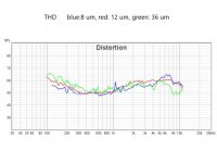
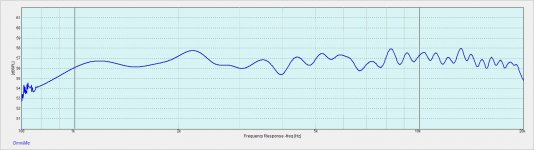
Here's how things change by varying the thickness of true pleated ribbons
Pleated_SPL
Pleated_THD
The dip in the SPL between 3 and 4 KHz is due, as usual, to the reflection from the table where the motor rests. We see that in the response there are significant differences only at the high frequencies, as was logical to expect. There is some reason to think about this, because the difference in SPL at 20 KHz of thick ribbons compared to thin ones is greater than what one would expect taking into account only the parasitic inductance, but this is another argument.
The THD instead, if you make the difference with the SPL levels, at high frequencies it doesn't change much, while at low frequencies it seems that 8 um is the best choice, but personally I would prefer 12 um because in my experience it seems to me that with 8 um it is more difficult to control the rattle.
For the avoidance of misunderstanding I want to clarify that when I speak of high THD in ribbons I mean relatively high, and not high in an absolute sense. In fact, looking at the 2 graphs, above 200 Hz the THD is still more than 40 dB below the SPL, which means less than 1% of distortion, with SPL = 100 dB at 1 KHz and mic at 6 cm, which corresponds approximately at 87 dB SPL with mic at 1m. I did not measure at higher levels because the Umik microphone starts to distort at low frequencies at 100 dB, and if you move it away different peaks will come out due to reflections from various nearby objects.
To avoid confusion, it is my intention to make comparisons between the following types of ribbons:
--- Different thicknesses
--- Single strip and multitrack
--- Embossed and pleated
--- Fine and coarse pleating
--- Suspension in tension and slow
The motor I will use is the one defined as engine A in post # 3.
Here's how things change by varying the thickness of true pleated ribbons
Pleated_SPL
Pleated_THD
The dip in the SPL between 3 and 4 KHz is due, as usual, to the reflection from the table where the motor rests. We see that in the response there are significant differences only at the high frequencies, as was logical to expect. There is some reason to think about this, because the difference in SPL at 20 KHz of thick ribbons compared to thin ones is greater than what one would expect taking into account only the parasitic inductance, but this is another argument.
The THD instead, if you make the difference with the SPL levels, at high frequencies it doesn't change much, while at low frequencies it seems that 8 um is the best choice, but personally I would prefer 12 um because in my experience it seems to me that with 8 um it is more difficult to control the rattle.
For the avoidance of misunderstanding I want to clarify that when I speak of high THD in ribbons I mean relatively high, and not high in an absolute sense. In fact, looking at the 2 graphs, above 200 Hz the THD is still more than 40 dB below the SPL, which means less than 1% of distortion, with SPL = 100 dB at 1 KHz and mic at 6 cm, which corresponds approximately at 87 dB SPL with mic at 1m. I did not measure at higher levels because the Umik microphone starts to distort at low frequencies at 100 dB, and if you move it away different peaks will come out due to reflections from various nearby objects.
Attachments

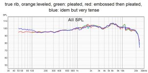
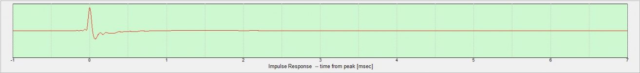
Below are the impulsive responses of true ribbons of different thicknesses, with unique damping with 3 cm foam behind:
True rib_8
True rib_12
True rib_36
The rise and fall times are better with the smaller thickness, but the overshoots and undershoots are less with the greater thickness.
True rib_8
True rib_12
True rib_36
The rise and fall times are better with the smaller thickness, but the overshoots and undershoots are less with the greater thickness.
Attachments


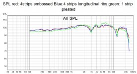
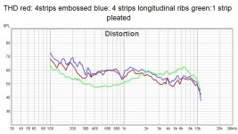
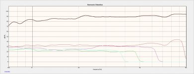
Now I compare the measurements on 3 different ribbons: all are made with Alu 12 um and a total of 27 mm wide, 2 are composed of 4 strips supported by 12 g / m ^ 2 paper, but the first is embossed and the second has 1 longitudinal rib on each strip. The third is a true ribbon with fine pleating in the center and coarse at the ends
Monostrip vs multistrip
monostrip vs multi_THD
The difference between the THDs of multistrip ribbons and true ribbon is evident and I must underline that this difference persists by changing various parameters such as stretching of the corrugations in the true ribbon or pleating of the 4 tracks instead of embossing. At frequencies below 2 KHz the THD is much better in true ribbon and this is understandable because the ribbon is stiffer in the transverse direction. Instead I don't understand why the THD is worse above 2 KHz (but still below 1%). I have tried to make some longitudinal cuts in the true ribbon but the distortion gets worse below 2 KHz and does not improve above.
Difference in impulse response: C21A, as mentioned above, is a 4 track with 12g / m ^ 2 embossed paper backing
C21A_5x25d35_comp_V
True rib_12
The impulse from the 4-track is much better. So if I had to make a tweeter I would certainly choose a multitrack tape, but for a mid-tweeter the choice is a matter of taste, and for a full range you have to make a separate speech. In fact, the measurements I made generally start from 100Hz or a little below, because to start from 30 Hz I would have had to reduce the volume by a lot in order not to deform the ribbon, or consider only ribbons with lateral suspensions, which in my opinion are the only ribbons which allow a full range without (or almost) rattle problems
Attachments


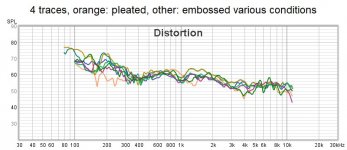
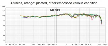
Now let's see the difference between pleating and embossement. I used 2 tapes: the first 4-track and the second true ribbon.
4 traces pleated vs embossed
4 traces pleated vs embossed_THD
The various conditions are: more or less taut ribbon, motor with 5 mm or 10 mm thick magnets. It seems that the pleating gives a little better results at low frequencies, but the effect is not striking and it is understandable because being 4 tracks the pleating does not stiffen the ribbon in all its width.
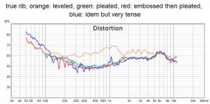
True ribbon
True rib_pleated vs embossed
True rib pleated vs embos_THD
It is clear that a smooth true ribbon is not worth it, and this too was to be expected.
The difference in the impulse response of a pleated ribbon compared to an embossed one is minimal, with a slight advantage for pleating
4 traces pleated vs embossed
4 traces pleated vs embossed_THD
The various conditions are: more or less taut ribbon, motor with 5 mm or 10 mm thick magnets. It seems that the pleating gives a little better results at low frequencies, but the effect is not striking and it is understandable because being 4 tracks the pleating does not stiffen the ribbon in all its width.
True ribbon
True rib_pleated vs embossed
True rib pleated vs embos_THD
It is clear that a smooth true ribbon is not worth it, and this too was to be expected.
The difference in the impulse response of a pleated ribbon compared to an embossed one is minimal, with a slight advantage for pleating
Attachments
Well hello ALL. Been a long time! Good to see ya all still at it ha. Thought I would just check in and to my surprise the ribbon distortion topic was on deck. I did do a lot of development work on this issue mostly because I wanted to take a smaller true “free swinging” ribbon to a lower crossover point. I see mention in this thred a number of things. Connections, mag field uniformity, ribbon construction, transformer construction, etc. While they all can have some effect on ribbon distortion, they all turned out to be minimal at best unless of course something was done really poorly.
In the end I did find a major contributor to ribbon distortion. In fact it was so big that once dealt with the distortion was an entire order of magnitude lower in this lower freq range. That’s right, an order of magnitude. Huge reduction BUT, well I will get to the “but” latter. The final design was a 75 mm long by 15 mm wide ribbon that could be crossed over at 1 khz with just a 2nd order filter without the large increase in distortion below about 2 khz typical in smaller free swinging ribbons. Basically I achieved distortion results at these lower freqs that compete with the better domes.
Understand however that I was really only concerned with distortion below about 2 Khz and only in smaller ribbons (100mm long or shorter). Above this freq the tech I developed had no effect BUT IMO above this freq a good ribbon is easily had with just some work on the diaphragms construction details and I wasn’t too concerned here. You can play with ribbon materials, thickness, corrugation size, adhesives, etc etc etc until u get a smooth response and that’s about it. Some work on the “slot” and face plate can help with response as well but again not a big contributor to distortion at volumes below about 100 db?. Not sure here but suspect diffraction at higher volumes can be an issue.
Basically the rising distortion with small ribbons taken to lower freqs are aero dynamic. Specifically at the ribbons edges. When the ribbon is called on to move larger distances, the ugly turbulence at the ribbons edge starts to be a problem. Once I discovered this I did some research and found that others have understood this in the past.
So why don’t we see designs out there that deal with it? Well for one the solutions they came up with are basically just making the “gap” between the ribbon edge and the magnet or pole piece very small thus reducing leakage and turbulence here. This is a very difficult and unforgiving way to overcome the turbulence at ribbon edge. U have to make a near perfectly straight ribbon, deal with the difficulty of aligning it at assembly into magnet, and when all done you can’t use it at lower freq ( unless u make a big one) because the ribbon scrapes the magnet at higher volumes due to instability. It’s effective BUT it’s far from practical for both manufacture and user. AND of course even IF you do find a practical way to build it you still have a fragile and poorly controlled diaphragm that will destroy itself at the lower freqs.
What was needed was twofold. 1- a practical way to deal with the turbulence at ribbon edge, and 2- a diaphragm design that won’t shred its self at lower freqs. Good luck with that.
Well it just so happened that the solution I came up with did both. 2 bird’s one stone. Holy Grail right?
Not so fast, we gota talk about the “BUT”. What I found, at least to my ears anyway is that although the distortion was significantly reduced, I did not hear a significant improvement in sound quality at “normal” listening volumes. I will call this crusing at around 90 db or so. At higher volumes it was noticeably better BUT is certainly wasn’t staggering. I suspect the type of distortion created by the turbulence isn’t all that big an issue perceptually.
The bigger value in the design was that now I have a reliable smaller ribbon that can go low. The significantly lower distortion was of value but not as much as I assumed it would be.
Now I would love to just tell ya all how I accomplished this but my plan is to sell the tech off down the road so I have to hold it. I have a patent written (not submitted) to go with it for anyone interested. However I have let the cat out of the bag with the turbulence thing so the DIY community can play with this area if it wants.
I see there is a company in Russia I think that has some very low distortion “ribbons” that can be crossed lower. Nice stuff and I don’t mean to cast negative here but I too played with that design years ago. Basically ya have a half roll surround at ribbon edge effectively eliminating the “gap” between ribbon edge and magnet. Great way to do it however in my own experiments I didn’t like the hash at the higher freqs that I believe go along with this basic structure. Obviously it’s a good tweeter but I wanted the faster decay I see with a true free swinging ribbon design.
Then of course there are the planer style drivers and the folded diaphragm designs that have no “gap”. Here too you can get low distortion at lower freqs and I made many protos of this type. However in the end they simply could not be made with all the sonic attributes of a free swing ribbon. They either had poor horizontal dispersion (diaphragm too wide), or their resonance at the lower crossover points colored the sound.
So Merry Christmas, I hope I’ve given ya some ideas to play with
In the end I did find a major contributor to ribbon distortion. In fact it was so big that once dealt with the distortion was an entire order of magnitude lower in this lower freq range. That’s right, an order of magnitude. Huge reduction BUT, well I will get to the “but” latter. The final design was a 75 mm long by 15 mm wide ribbon that could be crossed over at 1 khz with just a 2nd order filter without the large increase in distortion below about 2 khz typical in smaller free swinging ribbons. Basically I achieved distortion results at these lower freqs that compete with the better domes.
Understand however that I was really only concerned with distortion below about 2 Khz and only in smaller ribbons (100mm long or shorter). Above this freq the tech I developed had no effect BUT IMO above this freq a good ribbon is easily had with just some work on the diaphragms construction details and I wasn’t too concerned here. You can play with ribbon materials, thickness, corrugation size, adhesives, etc etc etc until u get a smooth response and that’s about it. Some work on the “slot” and face plate can help with response as well but again not a big contributor to distortion at volumes below about 100 db?. Not sure here but suspect diffraction at higher volumes can be an issue.
Basically the rising distortion with small ribbons taken to lower freqs are aero dynamic. Specifically at the ribbons edges. When the ribbon is called on to move larger distances, the ugly turbulence at the ribbons edge starts to be a problem. Once I discovered this I did some research and found that others have understood this in the past.
So why don’t we see designs out there that deal with it? Well for one the solutions they came up with are basically just making the “gap” between the ribbon edge and the magnet or pole piece very small thus reducing leakage and turbulence here. This is a very difficult and unforgiving way to overcome the turbulence at ribbon edge. U have to make a near perfectly straight ribbon, deal with the difficulty of aligning it at assembly into magnet, and when all done you can’t use it at lower freq ( unless u make a big one) because the ribbon scrapes the magnet at higher volumes due to instability. It’s effective BUT it’s far from practical for both manufacture and user. AND of course even IF you do find a practical way to build it you still have a fragile and poorly controlled diaphragm that will destroy itself at the lower freqs.
What was needed was twofold. 1- a practical way to deal with the turbulence at ribbon edge, and 2- a diaphragm design that won’t shred its self at lower freqs. Good luck with that
.Well it just so happened that the solution I came up with did both. 2 bird’s one stone. Holy Grail right?
Not so fast, we gota talk about the “BUT”. What I found, at least to my ears anyway is that although the distortion was significantly reduced, I did not hear a significant improvement in sound quality at “normal” listening volumes. I will call this crusing at around 90 db or so. At higher volumes it was noticeably better BUT is certainly wasn’t staggering. I suspect the type of distortion created by the turbulence isn’t all that big an issue perceptually.
The bigger value in the design was that now I have a reliable smaller ribbon that can go low. The significantly lower distortion was of value but not as much as I assumed it would be.
Now I would love to just tell ya all how I accomplished this but my plan is to sell the tech off down the road so I have to hold it. I have a patent written (not submitted) to go with it for anyone interested. However I have let the cat out of the bag with the turbulence thing so the DIY community can play with this area if it wants.
I see there is a company in Russia I think that has some very low distortion “ribbons” that can be crossed lower. Nice stuff and I don’t mean to cast negative here but I too played with that design years ago. Basically ya have a half roll surround at ribbon edge effectively eliminating the “gap” between ribbon edge and magnet. Great way to do it however in my own experiments I didn’t like the hash at the higher freqs that I believe go along with this basic structure. Obviously it’s a good tweeter but I wanted the faster decay I see with a true free swinging ribbon design.
Then of course there are the planer style drivers and the folded diaphragm designs that have no “gap”. Here too you can get low distortion at lower freqs and I made many protos of this type. However in the end they simply could not be made with all the sonic attributes of a free swing ribbon. They either had poor horizontal dispersion (diaphragm too wide), or their resonance at the lower crossover points colored the sound.
So Merry Christmas, I hope I’ve given ya some ideas to play with
Attachments
Last edited:
- Home
- Loudspeakers
- Planars & Exotics
- On the Distortion of Ribbon Speakers