A few years back I bought a pair of Adiostatic ESH100 speakers. A hybrid set of a conventional woofer for the low end and an electrostatic panel for the mid a high spectrum. I did a restoration job, you know reglueing and refoiling the electrostatic panels and fresh paint. When I powered them up I was really satisfied with the result achieved.
But in longer listening sessions I found out that one of the stats was somewhat lower in volume than the other one. Forum member mattstat provided me kindly with several very useful hints. One of them was his advice to check the bias supply. Because life stood in the way it took me a year to pay attention to the audiostatics again.
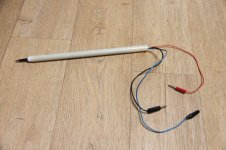
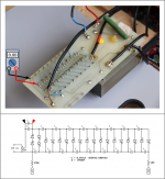
I diy'ed this simple bias measurement tool (picture). A 1 Gohm hv resistor in series with a 1 Mohm one and double isolation. I don't expect exact measurements but for comparing and adjusting bias voltages it should be okay.
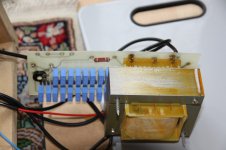
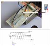
I couldn't find schematics of the ESH100 instead I found one of the ESH50 (picture). I also supplied several pictures of the inside and the electronics of the ESH100.
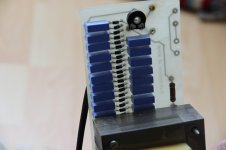
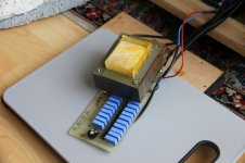
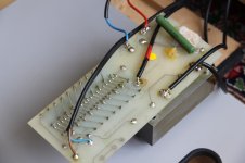
The transformer in picture 2 is the only one in this speaker.
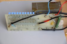
Brown and blue wire at the left in picture 3 is 220V power.
Black wire with red tape in pic 3 is hv to foil.
Blue and red wire in this picture (top right) are connected to woofer filter.
The two black wires at the bottom of the pcb are connected to the stators. In the last picture it is easier to see that there are two black wires.
My question: to prevent doing something stupid I would like to know how and where to measure bias. For instance where to attach the ground clip of my hv probe ? Should I measure with or without connected esl panel ?
But in longer listening sessions I found out that one of the stats was somewhat lower in volume than the other one. Forum member mattstat provided me kindly with several very useful hints. One of them was his advice to check the bias supply. Because life stood in the way it took me a year to pay attention to the audiostatics again.
I diy'ed this simple bias measurement tool (picture). A 1 Gohm hv resistor in series with a 1 Mohm one and double isolation. I don't expect exact measurements but for comparing and adjusting bias voltages it should be okay.
I couldn't find schematics of the ESH100 instead I found one of the ESH50 (picture). I also supplied several pictures of the inside and the electronics of the ESH100.
The transformer in picture 2 is the only one in this speaker.
Brown and blue wire at the left in picture 3 is 220V power.
Black wire with red tape in pic 3 is hv to foil.
Blue and red wire in this picture (top right) are connected to woofer filter.
The two black wires at the bottom of the pcb are connected to the stators. In the last picture it is easier to see that there are two black wires.
My question: to prevent doing something stupid I would like to know how and where to measure bias. For instance where to attach the ground clip of my hv probe ? Should I measure with or without connected esl panel ?
Attachments
Thanks for the ESH-100 pics.
Attached is a drawing showing where to connect your ground clip and place your HV probe tip. For safety, unplug the mains power before connecting or disconnecting the ground clip. I would measure each supply with the panel disconnected and with it connected. So 4 measurements in total. This should help isolate if the SPL difference is due to the power supply, due to leakage in the panel loading down the supply, or due to failing coating or coating contact.
Attached is a drawing showing where to connect your ground clip and place your HV probe tip. For safety, unplug the mains power before connecting or disconnecting the ground clip. I would measure each supply with the panel disconnected and with it connected. So 4 measurements in total. This should help isolate if the SPL difference is due to the power supply, due to leakage in the panel loading down the supply, or due to failing coating or coating contact.
Attachments
Last edited:
@bolserst, I did the measurements as you advised.
Because I'm somewhat scared of the high voltages involved
I put on rubber gloves.")
....................panel_connected panel_disconnected
Right speaker..........-4.2 kV.............-4.2 kV
Left speaker............-3.0 kV.............-3.0 kV
No difference between connected or disconnected panels but rather serious
difference in bias level between left and right.
Afaik the bias voltage of the Audiostatics should be about 5kV.
As I have learned that these measurements are just indicative I suppose
the right speaker is more or less correctly biased ????
Therefore I upped the bias of the left one. This made the left speaker way louder.
At the moment I think case closed.
Bolserst thank you again and also forum member mattstat who provided
me with useful clues in an earlier thread about my Audiostatics.
Because I'm somewhat scared of the high voltages involved
I put on rubber gloves.
....................panel_connected panel_disconnected
Right speaker..........-4.2 kV.............-4.2 kV
Left speaker............-3.0 kV.............-3.0 kV
No difference between connected or disconnected panels but rather serious
difference in bias level between left and right.
Afaik the bias voltage of the Audiostatics should be about 5kV.
As I have learned that these measurements are just indicative I suppose
the right speaker is more or less correctly biased ????
Therefore I upped the bias of the left one. This made the left speaker way louder.
At the moment I think case closed.
Bolserst thank you again and also forum member mattstat who provided
me with useful clues in an earlier thread about my Audiostatics.
I'm glad to hear you've made progress on the left/right imbalance and that our previous chats were helpful.
Given what you describe, assuming the right speaker is correctly biased makes sense.
As long as the woofer/electrostat balance seems right to your ears, I wouldn't worry about the apparent discrepancy between the Audiostatic specified bias level and what you are currently measuring. Increasing the bias too much will lead to instability, and another 800 volts wouldn't make a huge difference in output from where you are.
hmm nice ! that explains a few db , just enough to be annoyed it thought they where biased higher. so they both might be bad, there is a calculator since i suck at it where you can fill in the input voltage 230 nowadays, and the amount of stages. the amount of stages looks a bit like the solosounds and i thought they where biased towards the 5kv... but that might be a fable. maybe something interesting to check. then again if you are gone use new caps. you would do both anyways.
i used these cheap inverters for tube lights from conrad and a few stages of 1000 volt caps, you then can use a dc voltage to level them both to you liking (maybe one panel will be out of spec for instance)
TRU COMPONENTS 720004 Inverter voor koude kathode lampen 12 V/DC Aansluitkabel 1 stuk(s) | Conrad.nl
you can use the same method as in the original, but since you feed it a much higher voltage you do need to use higher voltage rated caps. you can then feed the inverter with a cheap dc power supply. if you can change the input dc voltage you can change the output HV voltage bias.
there is also a 500 volt version somewhere. you have to look for it. this is the 700 volt version. and you wont die touching it.. but i wont recommend how do i know ? .... but i cant promise anything haha so gloves is a good idea in any case, unless you want to trow whatever you hold in your hand across the room.
a few db , just enough to be annoyed it thought they where biased higher. so they both might be bad, there is a calculator since i suck at it where you can fill in the input voltage 230 nowadays, and the amount of stages. the amount of stages looks a bit like the solosounds and i thought they where biased towards the 5kv... but that might be a fable. maybe something interesting to check. then again if you are gone use new caps. you would do both anyways.i used these cheap inverters for tube lights from conrad and a few stages of 1000 volt caps, you then can use a dc voltage to level them both to you liking (maybe one panel will be out of spec for instance)
TRU COMPONENTS 720004 Inverter voor koude kathode lampen 12 V/DC Aansluitkabel 1 stuk(s) | Conrad.nl
you can use the same method as in the original, but since you feed it a much higher voltage you do need to use higher voltage rated caps. you can then feed the inverter with a cheap dc power supply. if you can change the input dc voltage you can change the output HV voltage bias.
there is also a 500 volt version somewhere. you have to look for it. this is the 700 volt version. and you wont die touching it.. but i wont recommend how do i know ? .... but i cant promise anything haha so gloves is a good idea in any case, unless you want to trow whatever you hold in your hand across the room.
Last edited:
Wrinex, the dutch book by Fikier indeed talks about 5kV bias for the Audiostatic. But the real value is difficult to measure because the moment you place the probe on the target point the voltage is dropping rapidly. Besides I didn’t calibrate my diy probe but measuring the ac wall outlet the outcome was too low.
@bolserst, I did the measurements as you advised.
....................panel_connected panel_disconnected
Right speaker..........-4.2 kV.............-4.2 kV
Left speaker............-3.0 kV.............-3.0 kV
No difference between connected or disconnected panels but rather serious
difference in bias level between left and right.
Afaik the bias voltage of the Audiostatics should be about 5kV.
…As I have learned that these measurements are just indicative I suppose
the right speaker is more or less correctly biased ?
Glad to hear you got the levels balanced out.

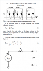
Yes, 4.2kV is roughly the correct value to read with a 1000Meg probe to indicate roughly +5kV when not loaded down by the probe. I meant to mention this, but forgot. The source impedance of the multiplier can be estimated fairly well with a simply formula based on the capacitor size, number of multiplier sections, and frequency of the AC input voltage. With 0.047uF caps, 50Hz AC, and 9 multiplier sections, the approximate source resistance is 223Meg. So if you measured 4.2kV with your 1000Meg probe, the unloaded output voltage would be:
Vout = Vmeasured * (223+1000)/1000 = 4.2*(223+1000)/1000 = 5.1kV
Another way to go about assessing the unloaded HV output, is to measure the voltage across the first capacitor in the multiplier string and then multiply that value by 18(2*number of sections) to get the theoretical final unloads output voltage. You should measure something in the range of 280-300VDC across the first capacitor. (See attached pic)
Attachments
- Home
- Loudspeakers
- Planars & Exotics
- Audiostatic ESH100 bias measurement