Why might my treble control go from 85% - 90% rather than 0 - 100%? Might it be a transformer or one of those mega ohm resistors?
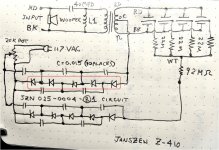
Here is my hand sketch wiring diagram:
Peter
I think this will work?
{\rtf1\ansi\ansicpg1252\cocoartf2580
\cocoatextscaling1\cocoaplatform1{\fonttbl\f0\fnil\fcharset0 .SFUI-Regular;}
{\colortbl;\red255\green255\blue255;\red49\green49\blue49;}
{\*\expandedcolortbl;;\cssrgb\c19216\c19216\c19216;}
\deftab720
\pard\pardeftab720\partightenfactor0
\f0\fs32 \cf2 \expnd0\expndtw0\kerning0
\outl0\strokewidth0 \strokec2 }
Last edited:
I can't see your wiring diagram.
If your interface is like the one I have, given what you've described I would suspect the 20 megaohm potentiometer on the output of the bias supply.
A few options to check it:
1) Swap the potentiometer from one speaker to the other and see if it fixes the problem. Discharge everything thoroughly first. Discharging is assumed in the next couple of suggestions also.
2) If you want to measure the potentiometer, you'll need to remove it from the circuit. Out of circuit, check its full resistance and also the readings from the wiper to each end as the position is changed.
3) You can substitute some fixed resistors in place of the pot and see if it then behaves correctly at various levels. There should be about 1200 volts DC coming out of the multiplier, so your resistors and/or meter need to handle that plus some extra for safety.
4) Assuming you don't have a voltmeter capable of reading the bias voltage, another diagnostic option would be to decrease the wall voltage with a variac and check the potentiometer's affect on the bias circuit at something like half the normal voltage. That should get you down into normal voltmeter range.
Since the bias is powered from wall voltage (mains electricity), there are potentially lethal voltages/currents inside. Be careful with whatever you decide to do.


")
A bad potentiometer reading wouldn’t mean they were bad if they were in the circuit. However, since they both read 0 - 20kohm okay while in place, I assumed they were fine. Since they were a bit scratchy, I later sprayed them with DeOxit both D and F.
To measure the -1100v, can I use a voltage divider? My DMM does go to 600v so I thought if I used a 10kohm and a 1kohm, then I should read about 1/10 of the voltage (or 1/11th) or should this be 10 ohms and 1 ohm or alternatively, 100 mohm and 10 mohms.
To measure the -1100v, can I use a voltage divider? My DMM does go to 600v so I thought if I used a 10kohm and a 1kohm, then I should read about 1/10 of the voltage (or 1/11th) or should this be 10 ohms and 1 ohm or alternatively, 100 mohm and 10 mohms.
Ouch!!! That high voltage supply is LIVE MAINS.
Suppose it´s acceptable, sort of, if it´s buried andinsulated inside your speakers with no way of touching it, but if you opened it and are measuring voltages, BE CAREFUL.
Given the speaker cost, not sure why they didn´t include an isolation transformer, which to boot would be quite small-inexpensive.
Oh well.
The adjustment circuit of your bias supply is different than the one I have.
I would still start by checking the potentiometer though. You can test its action under power by connecting your voltmeter to the wiper terminal and the pot's lower terminal in your drawing. Across those terminals, you should have varying AC voltage as the knob is turned (0-120 VAC). As stated previously, be careful. That is potentially lethal voltage/current. Using alligator test leads to clip your meter in while power is disconnected is one safer way to do this (you should have no hands near live circuits this way, though you can have stored energy in the capacitors).
High voltage probes for use with a DMM typically have a 1000 megaohm input impedance. This helps them minimally load the high voltage circuit and also handle the meter's input impedance properly.
High voltage multipliers like those used in most electrostatic speaker bias supplies can't typically provide much current, so loading them with external circuits/meters can pull the voltage down (line frequency ones more so).
Last edited:
Like I said previously, your supply is different than mine if you have a pot on the bias supply's input. That doesn't mean I doubt you, just that circuits change and yours isn't the same as mine. The potentiometer on mine is about 2 inches in diameter, has a brown Bakelite body, and its phenolic back has "20 MEG" stamped into it. A fixed resistor is soldered to the wiper terminal, and that feeds the bias to the panels.
No, the variation you're seeing in the individual panel current limiting resistors should not cause a volume difference if everything else is behaving normally. Those are typically carbon composition resistors that aren't tightly spec'd and they tend to drift a bit over time also. Carbon comps tend to do better with high voltage though, so that benefit often outweighs any other perceived deficiencies. Those resistors are there to help the panels operate in constant charge mode (reduces distortion) and to limit current in case of arcing. With a normally functioning panel the resistors can vary widely and not have any affect on output.
Are you talking about a volume difference from the left to right sets of panels or are you seeing volume differences within the group for one channel?
...To measure the -1100v, can I use a voltage divider? My DMM does go to 600v so I thought if I used a 10kohm and a 1kohm, then I should read about 1/10 of the voltage (or 1/11th) or should this be 10 ohms and 1 ohm or alternatively, 100 mohm and 10 mohms.
100 megohms or more is the load you can place on the bias supply and not over-load it. Accuracy not critical. A DVM can read 1:1000 ratio or higher with 1100v.
Take care, wear rubber boots and work with one arm in your pocket (actually, downstream the bias current is getting lower, but I would never risk contact). The 120v end is, of course, dangerous.
Why might my treble control go from 85% - 90% rather than 0 - 100%? Might it be a transformer or one of those mega ohm resistors?
...
Your speaker might sound OK with zero ESL output or at least "85%".
The "treble control"might be the pot on your diagram that adjusts the bias is to keep loudness up but popping or hissing down. Or is there an L-pad somewhere off your diagram?
ESLs make some sound with no bias, some retain their charge (or re-charge) with long timing (I've plotted mine for more than 10 hrs), and the effect of the control is hard to guess.
B.
Last edited:
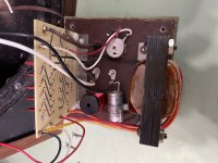
I burned up two about 1976 and Janszen sent me these two boards so they easily could be different. Mine has the little 1” silver pots that are so common. Nothing big and special.
The difference in volume seems to be between each panel. Some are tight and some are weak. i measured the resistance from all three brass nuts and everything measured good except for the 22mohm variation.
There is some gunk on some that I can’t identify. Kind of looks like a light mist of wax might have condensed on them. Not sure if it correlates to the sound level though.
Thank you,
Peter
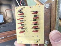
Hopefully, these are pictures of the circuit board before and after I recapped it and put on gold attachment connectors.

It bugged me that the red and black speaker connectors were run as black and white inside.

I changed wire colors and the 40mfd electrolytic cap to a polypropylene.
Peter
It bugged me that the red and black speaker connectors were run as black and white inside.
I changed wire colors and the 40mfd electrolytic cap to a polypropylene.
Peter
Last edited:
On individual panel problems:
The Janszen website says they still work on their older models, so that might be an option if things get beyond the limits of what you want to undertake yourself.
I've seen quite a few Janszen panels on eBay also. Quality and availability are highly variable, naturally.
The Janszen website says they still work on their older models, so that might be an option if things get beyond the limits of what you want to undertake yourself.
I've seen quite a few Janszen panels on eBay also. Quality and availability are highly variable, naturally.
Janzen and Dennesen have an interesting and quite distinguished place in HiFi history.
Focused on tweeters. Used plastic stators prolly scavenged from a lamp or something. The stator circuit carried by light gauge wires for example wrapped in spiral for round ones and held in place with hot glue.
Many ESL enthusiasts first heard the magic in their speakers. Basic speaker was like an AR-1 with ESL tweeters.
...Maybe, there is a charge on the plates and letting them dissipate over time is part of my problem.
REW and the mic in your laptop and all the tools you need to see the effect of the knob and time course.
B.
BTW, looking at the circuit, it seems the controls ought to be 0 - 100%. Maybe, there is a charge on the plates and letting them dissipate over time is part of my problem.
If ESLs are in good condition, there will be a significant discharge time. You can often speed it up by exhaling moist air on the coating side of the diaphragm...but of course this is only easy with a dipole ESL, or if the JansZen panels are mounted with coating side facing outward. Alternatively, turn the control all the way down and unplug the speaker overnight. Then when you go to test the next day, you will only be adding charge as you turn up the control so you won't have to wait for charge to leak away.
Thanks for posting the pics and schematic. Any chance of a pic showing the component side of the board?
Also, can you verify the orientation of the top string of diodes in the schematic? I think the orientation might need to be reversed.
Concerning the safety of direct mains powered HV mulitpliers...is the plug polarized? or can it be inserted into the socket in either orientation.
I assume there must be a fuse somewhere. Depending on it's location it could be affecting the available voltage if it has failed to a high impedance state.
I know the Audiostatic uses direct mains powered HV supplies in Europe, but used an isolation transformer and wallwart for US market.
AudioStatic ES-100 power
Attachments
Last edited:
Electrostatic components
Attached should be an image of the components and the wiring traces.
Curiously, I think I got the diode polarity correct but I’m not an electrical guy. In a note on his website, young Janszen mentioned the factory wiring diagrams got the polarity defined incorrectly.
Ha. Maybe I’m right or maybe I’m in good company.
Peter
Attachments
- Home
- Loudspeakers
- Planars & Exotics
- Janszen Z-410 sound issues