Hi, last week I finished my fifth pair of electrostatic loudspeakers. (see attachments #5 and #6) I think it's the best effort of my five attempts.
Sensitivity is around 86 dB / 1m / 1 VA / 1 kHz. Outer dimensions are 40 cm x 150 cm. Diaphragm (mylar) thickness is 6 micron and dimensions are 23 x 130 cm. Stator / membrane spacing is about 1,6 mm, a little less than I used in previous models. (about 2,4 mm). I'm aware this limits maximum excursion, but has the benefit of improved sensitivity. I use a custom made 1:125 full range quality setup transformer.
I use loudspeaker screen on the front because otherwise the panels don't fit esthetically with my room. This dampened the fundamental resonance frequency with 5 dB. After fitting a mesh damping screen with a rather low rayle number on the rear stator (on the inner side of the wire stator in order to damp resonances in mid range as well), I got around 2,5 dB more damping, resulting in 7 to 8 dB damping. Resonance frequencies of both panels are 62 and 76 Hz. I guess they will lower a bit after breaking in. I hope they will stabalize around 50 Hz.
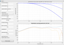
I used the software "esl_seg_ui" by Edo Hulsebos to simulate / calculate the electrical segmentation. (see attachements #1)
In the simulation I included the 1 Ohms series resistor between amplifier and audio transformer.
I did extensive listening tests in the room where I built the speakers which is a smaller room than my living room where I put them after they were finished. Bass extension was ok in the smaller room, but in my larger (26 square meters) room at greater listening distance (5 meters from speakers) it feels a bit thin. Not too bad, but I would like to have a bit more lf extension / power.
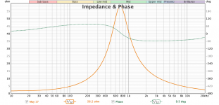
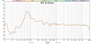
For frequency and impedance measurements, see attachements #2 and #3.
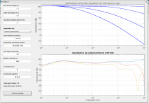
Instead of building another, larger pair of speakers I was thinking about adding an extra panel per channel which serves as a bass panel to improve bass extension. By putting two panels per channel close to each other airload increases resulting in lowering of resonance frequency. So I'm considering to build another pair with same dimensions and use the same amount of wires (64 per panel) and connect them to the other, segmented panels by adding 1 resistor which makes a low-pass filter. The only possible disadvantage could be that this lf segment is not symetrically on both sides of the main panel, but on only 1 side. Would this be a problem? I made another simulation using esl_seg_ui by adding this new panel by adding one new wire group of 32 wires (2x 32 in this simulation equals 1 new seperate bass panel of 64 wires). See attachements #4.
Included attachements:
#1: segmentation simulation for current panel
#2: impedance and phase measurement in REW, using a custom 1:125 step-up transformer and a 1 Ohms series resistor
#3: frequency measurement in REW with microphone close to front stator (about 3 cm)
#4: segmentation simulation for current + new bass panel
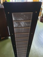
#5: rear side of new panel
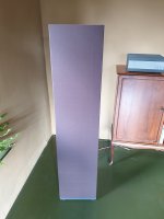
#6: front side of new panel
Sensitivity is around 86 dB / 1m / 1 VA / 1 kHz. Outer dimensions are 40 cm x 150 cm. Diaphragm (mylar) thickness is 6 micron and dimensions are 23 x 130 cm. Stator / membrane spacing is about 1,6 mm, a little less than I used in previous models. (about 2,4 mm). I'm aware this limits maximum excursion, but has the benefit of improved sensitivity. I use a custom made 1:125 full range quality setup transformer.
I use loudspeaker screen on the front because otherwise the panels don't fit esthetically with my room. This dampened the fundamental resonance frequency with 5 dB. After fitting a mesh damping screen with a rather low rayle number on the rear stator (on the inner side of the wire stator in order to damp resonances in mid range as well), I got around 2,5 dB more damping, resulting in 7 to 8 dB damping. Resonance frequencies of both panels are 62 and 76 Hz. I guess they will lower a bit after breaking in. I hope they will stabalize around 50 Hz.
I used the software "esl_seg_ui" by Edo Hulsebos to simulate / calculate the electrical segmentation. (see attachements #1)
In the simulation I included the 1 Ohms series resistor between amplifier and audio transformer.
I did extensive listening tests in the room where I built the speakers which is a smaller room than my living room where I put them after they were finished. Bass extension was ok in the smaller room, but in my larger (26 square meters) room at greater listening distance (5 meters from speakers) it feels a bit thin. Not too bad, but I would like to have a bit more lf extension / power.
For frequency and impedance measurements, see attachements #2 and #3.
Instead of building another, larger pair of speakers I was thinking about adding an extra panel per channel which serves as a bass panel to improve bass extension. By putting two panels per channel close to each other airload increases resulting in lowering of resonance frequency. So I'm considering to build another pair with same dimensions and use the same amount of wires (64 per panel) and connect them to the other, segmented panels by adding 1 resistor which makes a low-pass filter. The only possible disadvantage could be that this lf segment is not symetrically on both sides of the main panel, but on only 1 side. Would this be a problem? I made another simulation using esl_seg_ui by adding this new panel by adding one new wire group of 32 wires (2x 32 in this simulation equals 1 new seperate bass panel of 64 wires). See attachements #4.
Included attachements:
#1: segmentation simulation for current panel
#2: impedance and phase measurement in REW, using a custom 1:125 step-up transformer and a 1 Ohms series resistor
#3: frequency measurement in REW with microphone close to front stator (about 3 cm)
#4: segmentation simulation for current + new bass panel
#5: rear side of new panel
#6: front side of new panel
Attachments
Last edited:
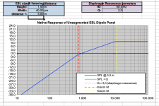
In addition to my previous post, I found an very useful excel sheet by Bolserst to calculate far / near field, and intermediate field. Although I was aware of this sheet, I never seriously applied it. See post below:
https://www.diyaudio.com/forums/planars-and-exotics/206816-segmented-wire-stator-esl-simulator-esl_seg_ui-2.html#post2913884
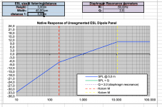
Tonight I filled in the dimensions of my latest stats (I used the outer dimensions of the panel, not the diaphragm dimensions), see attachement #1. I used a listening position of 5 meters as this reflects my current situation. In this case the intermediate field ranges from 756 Hz to 10625 Hz. So that would result in a -3 dB/oct slope below 756 Hz, as I used electrical segmentation calculated / simulated by esl_seg_ui. Resonance frequency at around 60 Hz corrects this dip a little bit. Above 10 kHz there would be a +3 dB slope, but LC resonance of audio transformer + panel, and weight of the 6 micron mylar will compensate for this raise in output at higher frequencies.
In order to extend low frequency range, (it's not a big deal, but I would think this would make an improvement because of the increased listening position) I'm wondering what would be the best option, if I want to build a second panel per channel: put it next to the current panel as described in my first post, and use this panel as a bass (only) panel, or just copy the current panel (and it's segmentation) and put it on top of the current panel? In the last case, this would get closer to a line-source.
Widening the panel would result in a graph in attachement #2: the near field (yellow dashed line) moves to the left, resulting in a field transition point at 2656 Hz. So, assumed I apply segmentation as suggested by esl_seg_ui, as proposed in my previous post, I would get a +3 dB/oct slope from 2656 Hz upwards. The -3 dB/oct slope in the far field region doesn't change. To me, this seems not answering my wish to extend low frequency range, but rather boost mid / high frequencies.
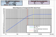
Doubling height of the panel, and keeping width the same would result in a graph in attachement #3: this lowers the field transition point (red dashed line) down to 189 Hz and keeping the other transition pont (yellow dashed line) at 10625 Hz. This would increase low frequency range with approximately +6 dB. (two ocatves @ 3 dB/oct: 756/2/2=189Hz)
I'm not sure if I made any errors or forgot things (like core saturation, etc.), but at the moment I would conclude that stacking both panels vertically would be preferable as this would extend low frequency range and would come closer to a true line source?
https://www.diyaudio.com/forums/planars-and-exotics/206816-segmented-wire-stator-esl-simulator-esl_seg_ui-2.html#post2913884
Tonight I filled in the dimensions of my latest stats (I used the outer dimensions of the panel, not the diaphragm dimensions), see attachement #1. I used a listening position of 5 meters as this reflects my current situation. In this case the intermediate field ranges from 756 Hz to 10625 Hz. So that would result in a -3 dB/oct slope below 756 Hz, as I used electrical segmentation calculated / simulated by esl_seg_ui. Resonance frequency at around 60 Hz corrects this dip a little bit. Above 10 kHz there would be a +3 dB slope, but LC resonance of audio transformer + panel, and weight of the 6 micron mylar will compensate for this raise in output at higher frequencies.
In order to extend low frequency range, (it's not a big deal, but I would think this would make an improvement because of the increased listening position) I'm wondering what would be the best option, if I want to build a second panel per channel: put it next to the current panel as described in my first post, and use this panel as a bass (only) panel, or just copy the current panel (and it's segmentation) and put it on top of the current panel? In the last case, this would get closer to a line-source.
Widening the panel would result in a graph in attachement #2: the near field (yellow dashed line) moves to the left, resulting in a field transition point at 2656 Hz. So, assumed I apply segmentation as suggested by esl_seg_ui, as proposed in my previous post, I would get a +3 dB/oct slope from 2656 Hz upwards. The -3 dB/oct slope in the far field region doesn't change. To me, this seems not answering my wish to extend low frequency range, but rather boost mid / high frequencies.
Doubling height of the panel, and keeping width the same would result in a graph in attachement #3: this lowers the field transition point (red dashed line) down to 189 Hz and keeping the other transition pont (yellow dashed line) at 10625 Hz. This would increase low frequency range with approximately +6 dB. (two ocatves @ 3 dB/oct: 756/2/2=189Hz)
I'm not sure if I made any errors or forgot things (like core saturation, etc.), but at the moment I would conclude that stacking both panels vertically would be preferable as this would extend low frequency range and would come closer to a true line source?
Attachments
Last edited:
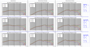
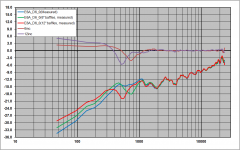
Since the spreadsheet is calculating field transition break-points for an unsegmented ESL far away from any room boundary, it can be difficult to draw conclusions for segmented ESLs in a room. To get a better idea of the difference between adding width and adding height, we can compare a theoretical infinite line with a finite ESL line source, as well as a finite line sitting on the floor receiving contribution from the floor mirror image source. I believe the 3rd case is closest to what you have.
Attachment #1: This set of plots shows response for the 3 line source models (ideal, finite, and finite-on-floor) for your original panel, and then with doubling width, or height. For the double width, I used a lower ladder resistance value that you had so as to lift the LF response for the finite-on-floor. For the double height, I hooked the segments together, so same segment widths but twice the height requiring the ladder resistors to be halved. Both doubling width and height can provide improved LF response with little effect on the HF polar response.
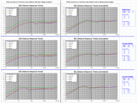
Attachment #2: One other thing to look at when evaluating adding height or width, is how the response changes with distance from the ESL. Adding height reduces the variability of the LF response(<200Hz) with varying distance. This is one of the reasons I prefer to add height rather than width. It also happens to take up less floor space. But some people feel the added height makes them dominate a room's decor, and so prefer a shorter, wider panel from an aesthetic standpoint.
Attachment #1: This set of plots shows response for the 3 line source models (ideal, finite, and finite-on-floor) for your original panel, and then with doubling width, or height. For the double width, I used a lower ladder resistance value that you had so as to lift the LF response for the finite-on-floor. For the double height, I hooked the segments together, so same segment widths but twice the height requiring the ladder resistors to be halved. Both doubling width and height can provide improved LF response with little effect on the HF polar response.
Attachment #2: One other thing to look at when evaluating adding height or width, is how the response changes with distance from the ESL. Adding height reduces the variability of the LF response(<200Hz) with varying distance. This is one of the reasons I prefer to add height rather than width. It also happens to take up less floor space. But some people feel the added height makes them dominate a room's decor, and so prefer a shorter, wider panel from an aesthetic standpoint.
Attachments
If you attach "wings" to each side of the panel pointing for example 45deg backwards, and they have an extension length same as the 1/2 with of the panel you should get +6dB in the low end. I have experimented with this on esl 63s and the extra bass you get is distortion free, flat, clean punchy extra bass, "for free", extending the further gives some more dB. If you look at bolserst graph at 10 Hz you clearly see which one to go for. If you want clean, good bass response.
@esl 63: thanks for your wings suggestion, I will try / experiment by adding some wings to the current stats.
@Bolsterst: thanks again for your help and simulations. Can your excel sheets for these simulations be found on this forum?
I agree on your conclusion that making a panel taller seems preferable when looking at your simulations, although it differs "only" a few dB's.
The only thing I'm wondering is when making the current design taller, let's say about 2.5 meters tall rather than the current 1.5 meters (as 3 meters is a little too tall maybe), capacitance will raise and LC resonance of panel and transformer will lower in frequency. I tested this by connecting 2 panels in parallel to 1 transformer and measured 5 cm in front of one stator and I can see a reduced high frequency roll-off.
In order to keep high frequency range about the same, would proportionally increasing d/s distance compensate for this? (as panel capacitance will be the same as the smaller panel)?
Yes, if capacitance from 2.5m tall ESL is an issue for your transformers, you could reduce capacitance by increasing d/s distance.
Alternatively, you could reduce the segments widths. Or, if you already have DSP in the signal chain, you could use it to flatten the top end.
Not much concern about boosting highs as there is little musical content up there.
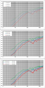
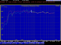
Sorry, the simulation spreadsheet has not been posted yet. I have been working on an expanded capability segmented ESL spreadsheet that includes polar maps and everything from transformer parasitic, to room boundary reflections, stator transparency, and damping mesh. But, it is not near user friendly enough to post yet. Your question did remind me though, that I had performed some measurements of a finite line source ESL suspended in a gymnasium to confirm I had calculations working properly.
Attachment #1 is a comparison of theory and measurement for a 64” x12” line source measured at 3ft, 6ft, and 9ft.
While looking for that measurement, I found another one where I had measured the effects of adding wings to an ESL panel.
Attachment #2 shows measurements and calculated increment for adding 6” and 12” wings to a 12” wide ESL.
So you get a nice LF boost, but can start impacting the midrange if taken too far. eAudiostatic baffle step filter
I thought you had tried wings previously and didn’t like the results…but I could easily be confusing you with another diyAudio member.
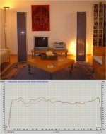
Attachment #3 shows room average response with and without wings from a while ago.
The LF boost is as expected, and the midrange notch shown in previous windowed measurements is not quite as prominent since its frequency and depth changes with off-axis angle and smooths out in a time averaged room response.
Some years ago, Capaciti posted a similar measurement for his Element 160 with Plexiglas wings. Some questions on ESL dimensions
Although he didn’t post a picture of the ESL, I had saved an image from his website which I included here as Attachment #4 .
Alternatively, you could reduce the segments widths. Or, if you already have DSP in the signal chain, you could use it to flatten the top end.
Not much concern about boosting highs as there is little musical content up there.
Sorry, the simulation spreadsheet has not been posted yet. I have been working on an expanded capability segmented ESL spreadsheet that includes polar maps and everything from transformer parasitic, to room boundary reflections, stator transparency, and damping mesh. But, it is not near user friendly enough to post yet. Your question did remind me though, that I had performed some measurements of a finite line source ESL suspended in a gymnasium to confirm I had calculations working properly.
Attachment #1 is a comparison of theory and measurement for a 64” x12” line source measured at 3ft, 6ft, and 9ft.
While looking for that measurement, I found another one where I had measured the effects of adding wings to an ESL panel.
Attachment #2 shows measurements and calculated increment for adding 6” and 12” wings to a 12” wide ESL.
So you get a nice LF boost, but can start impacting the midrange if taken too far. eAudiostatic baffle step filter
I thought you had tried wings previously and didn’t like the results…but I could easily be confusing you with another diyAudio member.
Attachment #3 shows room average response with and without wings from a while ago.
The LF boost is as expected, and the midrange notch shown in previous windowed measurements is not quite as prominent since its frequency and depth changes with off-axis angle and smooths out in a time averaged room response.
Some years ago, Capaciti posted a similar measurement for his Element 160 with Plexiglas wings. Some questions on ESL dimensions
Although he didn’t post a picture of the ESL, I had saved an image from his website which I included here as Attachment #4 .
Attachments
That looks really nice ! very slick !
I wonder why are there so many Dutch people making ESL's small country but allot of diy") love it !! would love to meet and hear and see some of all these builds !
love it !! would love to meet and hear and see some of all these builds !
may i ask where you are located? im living in Den Haag by the way
I wonder why are there so many Dutch people making ESL's small country but allot of diy
love it !! would love to meet and hear and see some of all these builds !may i ask where you are located? im living in Den Haag by the way
Last edited:
I'd love to see additional photos on how the stators - grid and frame was put together if you care to share them. They look great!
Hi, I didn't make that much photos unfortunately during the production process as it's like a repitition of previous made models, but with a few changes. I am planning to build a new - taller - model and I will make pictures and publish them here. So just keep checking this forum - it can take 6 to 12 months before I expect to finish the next model.
To summarize, I used a smaller d/s distance to get a good sensitivity and at the same time not a to big panel to make it esthetically pleasing. I used a combination of front grille and mesh screen on the back (with a relatively low air resistance / rayle number) in order to fight Q / resonance and at the same time protect the diaphragm from attracting too much dust. It also keeps people from touching the wires as this is something what happens sometimes if people try to understand how this thing is working / built.
That looks really nice ! very slick !
I wonder why are there so many Dutch people making ESL's small country but allot of diy
may i ask where you are located? im living in Den Haag by the way
Hi WrineX, I live in the very north of the Netherlands, Warffum. You are always welcome to visit my place and have an extensive listening session!
@Bolserst: thanks again for your help, I tend to go for a taller panel, for my next, #6 project and proportionally increase d/s distance to keep panel capacitance about equal to the #5 panel in order to maintain high frequency extension. Making the width of the pannel smaller would maybe an option as well - but in that case I need to change electrical segmentation.
Some pics were posted for one of his previous builds:I'd love to see additional photos on how the stators - grid and frame was put together if you care to share them.
My new stats, model #4
Hi, I didn't make that much photos unfortunately during the production process as it's like a repitition of previous made models, but with a few changes. I am planning to build a new - taller - model and I will make pictures and publish them here. So just keep checking this forum - it can take 6 to 12 months before I expect to finish the next model.
Thanks, I'll look forward very much to seeing more photos.
Hi again. It has been a while ago since I wrote about my latest model and got some extensive help from bolserst with simulations which seem to answer my question about whether to extend the next model either in height or width: I will extend it in height as this reduces variability of the LF response(<200Hz) compared to extending in width.
I think the ceiling height is at around 300 cm. So maximum total length will be 300 cm. But my girlfriend doesn't like that idea esthetically. So I could pick a size somewhere in between the current total height of 150 cm and 300 cm, like 240 cm. If I'm correct this will give a LF boost of 4 dB. (instead of 6 dB for doubling the length to 300 cm)
Would 4 dB LF gain be worth the (big) effort of building a new pair of stats?
Another question / idea I came up with is this: it seems all about making compromises. If I extent height, I raise capacity and I lower HF range because of LC resonance of panel + transformer. So I can compensate for this by raising d/s distance to correct capacity to the capacity of the current panel. But if I'm correct, sensitivity decreases by a factor of 4. So when I double the height to 300 cm, I need to double d/s distance, which makes the panel 4 times less sensitive. If I'm correct about this, this sounds problematic as sensitivity is already limited compared to dynamic loudspeakers, somewhere around 86 dB / 1m / 1 VA / 1 kHz (at max, 1 channel lost a few dB's it seem...).
So raising d/s distance seems an unattractive option to me.
I did a lot of extensive listening test by connecting my DIY Scanspeak Event (http://speakerenco.nl/Products/ScanSpeak-Event) transmissionline loudspeakers to my DSP so I was able to switch between DIY esl panels and dynamic loudspeaker. I learned that coherence between the whole frequency range was (much) better for the stats compared to the event loudspeakers. But below 50 Hz the stats don't produce much output while the loudspeakers have a bump around 25 Hz creating a lot of energy. Also HF extension is better for the loudspeakers compared to my stats. This is due to the rather large transformers which I expect to have no core saturation problems (1:125 step up), but are limited in HF output with my current panels. (they will fall off after 12-13 kHz).
So to summarize I think everything between 50 and 12 kHz sounds (very) good, but LF and HF extension are limited for my stats, even though I get compliments of stat owners who tell me they deliver more LF than they would expect. And only on rare occasions I really miss LF range like in organ music.
So when keeping the same transformers I have to increase d/s distance and loose sensitivity as a result to maintain the same HF range. I will win, depending on height extension up to 6 dB at max.
But last week I got the following idea which is both expensive and laborious, but will (I think) extend both LF and HF range: how about splitting 1 tall panel into 2 separate panels? Resonance frequency will be lowered, if I'm correct, as this depends on air mass and membrane tension (https://www.diyaudio.com/community/threads/esl-diaphragm-tension.374992/#post-6737087), so coupling two panels will still reduce resonance frequency which is something I want to happen as current panels have a resonance frequency of around 65 Hz which limits LF output below 65 Hz. It will be easier to work on 2 smaller panels compared to one very tall panel. If I take 2 transformers per channel rather than 1, and 2 power amplifiers per channel, I will gain 6 dB of sensitivity compared to my current panel setup. I can compromise on sensitivity by lowering step-up ration of the transformers: if I reduce step up with 50% to 1:60, I get 0 dB sensitivity gain, but I will get a higher LC resonance resulting in better HF extension.
So my idea is to get 4 custom made transformers, around 1:60 - 1:80 step up ratio, which don't saturate too soon, combined with power amps for 4 channels, powering 2 panels per channel. This will:
Any ideas / warnings / suggestions about this idea? There's at least 1 certainty: it will cost quite some money and labour to implement. So I'm very curious about your opinions.
I think the ceiling height is at around 300 cm. So maximum total length will be 300 cm. But my girlfriend doesn't like that idea esthetically. So I could pick a size somewhere in between the current total height of 150 cm and 300 cm, like 240 cm. If I'm correct this will give a LF boost of 4 dB. (instead of 6 dB for doubling the length to 300 cm)
Would 4 dB LF gain be worth the (big) effort of building a new pair of stats?
Another question / idea I came up with is this: it seems all about making compromises. If I extent height, I raise capacity and I lower HF range because of LC resonance of panel + transformer. So I can compensate for this by raising d/s distance to correct capacity to the capacity of the current panel. But if I'm correct, sensitivity decreases by a factor of 4. So when I double the height to 300 cm, I need to double d/s distance, which makes the panel 4 times less sensitive. If I'm correct about this, this sounds problematic as sensitivity is already limited compared to dynamic loudspeakers, somewhere around 86 dB / 1m / 1 VA / 1 kHz (at max, 1 channel lost a few dB's it seem...).
So raising d/s distance seems an unattractive option to me.
I did a lot of extensive listening test by connecting my DIY Scanspeak Event (http://speakerenco.nl/Products/ScanSpeak-Event) transmissionline loudspeakers to my DSP so I was able to switch between DIY esl panels and dynamic loudspeaker. I learned that coherence between the whole frequency range was (much) better for the stats compared to the event loudspeakers. But below 50 Hz the stats don't produce much output while the loudspeakers have a bump around 25 Hz creating a lot of energy. Also HF extension is better for the loudspeakers compared to my stats. This is due to the rather large transformers which I expect to have no core saturation problems (1:125 step up), but are limited in HF output with my current panels. (they will fall off after 12-13 kHz).
So to summarize I think everything between 50 and 12 kHz sounds (very) good, but LF and HF extension are limited for my stats, even though I get compliments of stat owners who tell me they deliver more LF than they would expect. And only on rare occasions I really miss LF range like in organ music.
So when keeping the same transformers I have to increase d/s distance and loose sensitivity as a result to maintain the same HF range. I will win, depending on height extension up to 6 dB at max.
But last week I got the following idea which is both expensive and laborious, but will (I think) extend both LF and HF range: how about splitting 1 tall panel into 2 separate panels? Resonance frequency will be lowered, if I'm correct, as this depends on air mass and membrane tension (https://www.diyaudio.com/community/threads/esl-diaphragm-tension.374992/#post-6737087), so coupling two panels will still reduce resonance frequency which is something I want to happen as current panels have a resonance frequency of around 65 Hz which limits LF output below 65 Hz. It will be easier to work on 2 smaller panels compared to one very tall panel. If I take 2 transformers per channel rather than 1, and 2 power amplifiers per channel, I will gain 6 dB of sensitivity compared to my current panel setup. I can compromise on sensitivity by lowering step-up ration of the transformers: if I reduce step up with 50% to 1:60, I get 0 dB sensitivity gain, but I will get a higher LC resonance resulting in better HF extension.
So my idea is to get 4 custom made transformers, around 1:60 - 1:80 step up ratio, which don't saturate too soon, combined with power amps for 4 channels, powering 2 panels per channel. This will:
- extend LF by 4-6 dB, depending on height extension
- extend HF
Any ideas / warnings / suggestions about this idea? There's at least 1 certainty: it will cost quite some money and labour to implement. So I'm very curious about your opinions.
Last edited:
Have you tried simulating this boost with equalization? You won't be able to play at maximum volume with this technique, but you could compare the ESL's with and without the amount of boost you think you are going to get with your new panels to get a better feel for what 4 dB of gain gets you in the frequency range of interest.Would 4 dB LF gain be worth the (big) effort of building a new pair of stats?
There's at least 1 certainty: it will cost quite some money and labour to implement. So I'm very curious about your opinions.
It appears you are wanting to compensate for inherent weaknesses of the ESL panels by going bigger with more panels but with limited expected gain costing time and mone. That strategy seems really challenging as the fundamental weakness in LF and HF remains. Is it worth thinking about heading in the opposite direction? Add a non-ESL transducer that has strengths in the areas the ESL struggle with.
You already have a dynamic speaker that does well in the very LF and very HF where the panels are compromised. The ESL excel between the frequency extremes. They look like a perfect match Why not just use them together? Use a digital crossover for sophisticated crossovers with timing compensation and you can dial in a really smooth transition and get the response you want. Do you have a spare amp and DSP's?
Last edited:
And your step response will still be ruined.It appears you are wanting to compensate for inherent weaknesses of the ESL panels by going bigger with more panels but with limited expected gain costing time and mone. That strategy seems really challenging as the fundamental weakness in LF and HF remains. Is it worth thinking about heading in the opposite direction? Add a non-ESL transducer that has strengths in the areas the ESL struggle with.
You already have a dynamic speaker that does well in the very LF and very HF where the panels are compromised. The ESL excel between the frequency extremes. They look like a perfect match Why not just use them together? Use a digital crossover for sophisticated crossovers with timing compensation and you can dial in a really smooth transition and get the response you want. Do you have a spare amp and DSP's?
Thanks for your input. I could do with some help understanding this please. I tried a similar thing once as a silly joke running ESL with a dynamic together. Weird thing is it sounded really good despite no digital time correction. I'm sure your correct that measurements at the listening position would have shown horrible timing effects. Maybe most combinations would sound awful. I probably just got lucky. But if using digital DSP's with timing compensation would you still expect the "step response will still be ruined"?And your step response will still be ruined.
- Home
- Loudspeakers
- Planars & Exotics
- My newest pair of DIY electrostatic panels, advice needed