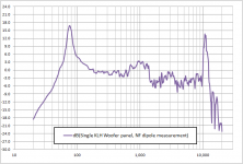
Hi, I have been troubled by un / under damped fundamental resonances for a long time. My latest stats, model #4, have printing mesh screens on the rear side to tame the fundamental resonance which is currently at 19 Hz. I will publish my new measuring results soon as I tried a new screen with higher rayle / resistance. The problem is, in my opinion, that a better damping results in poorer mid / high frequency quality.
As the sensitivity of my bigger panels are limited as well, I decided to build a new model, #5, of which I will start a new topic here in future. But I would like to try to build the electrostatic panel without damping screen. It measures 40 x 150 cm outer dimensions, diaphragm dimensions are 23 x 130 cm. I built a pair of ripole woofers similar to the ones Charlie (Jazzman) built.
My question: can one build undamped esl panels, combining them with electromagnetic (sub)woofers without the subwoofers exciting the esl panel resonance(s)?
The crossover frequency will be 80 to 100 Hz, @48 dB/oct (DSP), and the esl panel resonance will be between 40 and 50 I estimate.
Hi,
possible? Yes, of course its possible")
Your concept imho bears some flaws though.
a) The mantra of good ESLs -at least that applies to hybrids- is efficiency, efficiency, and yet again efficiency
This means to omit with the low-as-possible resonance thinking.
It´s a quite common misconception that a low resonance point is any good ... but it certainly isn´t.
A resonance point of 150Hz and even higher is way more beneficial for the sonic outcome than the putative backdraws of a higher x-over frequency.
The peaking at the resonance point does increase with the higher mechanical tension of the diaphragm, but can be tamed effectively either mechanically with a mesh or electronically using a precise notch filter.
b) build the panel as large as possible.
There´s no good reason to have only 23x130cm of diaphragm area when almost 40x150cm are possible ... nearly double the area!!
No baffle extension will give you any useful increase in ouput ... but larger membrane area does.
Besides that a large panel fitted to a reduced frame will be optically more pleasing than a small panel in a wide frame.
Dipole woofers are the naturally born partners for open baffle speaker systems.
And dipole towers are the best fit to tall, slim ESL panels.
You will have to work with rather small drivers and small baffle dimensions to achieve the required high upper bandwidth limit and to reduce negative effects at the x-over point like combing freq-response.
This will most certainly ask for folded baffle type of dipole woofers as they allow for the smallest builds.
If You choose the parameters well, the resultant amplitude response of the woofer (above its chamber resonance) could mirror that of the panel, thereby reducing the burdon on electronic filtering ... corrective filtering like notching etc. of more than +-6dB seems to become audible, regardless of the useage of analog or digital filtering.
Placed in the dipole null of the woofer the panel will see a pressure null, which is a velocity pole at the same.
A small gap between woofer cabinet and panel is required ... 2-3cm is sufficient ... to effectively reduce the flapping-in-the-breeze of the ESL-membrane (the coupling is not completely nulled, but only reduced just enough)
To close the circle ... possible? Yes, and if You juggle the parameters right its a big big big Yes
jauu
Calvin
possible? Yes, of course its possible
Your concept imho bears some flaws though.
a) The mantra of good ESLs -at least that applies to hybrids- is efficiency, efficiency, and yet again efficiency
This means to omit with the low-as-possible resonance thinking.
It´s a quite common misconception that a low resonance point is any good ... but it certainly isn´t.
A resonance point of 150Hz and even higher is way more beneficial for the sonic outcome than the putative backdraws of a higher x-over frequency.
The peaking at the resonance point does increase with the higher mechanical tension of the diaphragm, but can be tamed effectively either mechanically with a mesh or electronically using a precise notch filter.
b) build the panel as large as possible.
There´s no good reason to have only 23x130cm of diaphragm area when almost 40x150cm are possible ... nearly double the area!!
No baffle extension will give you any useful increase in ouput ... but larger membrane area does.
Besides that a large panel fitted to a reduced frame will be optically more pleasing than a small panel in a wide frame.
Dipole woofers are the naturally born partners for open baffle speaker systems.
And dipole towers are the best fit to tall, slim ESL panels.
You will have to work with rather small drivers and small baffle dimensions to achieve the required high upper bandwidth limit and to reduce negative effects at the x-over point like combing freq-response.
This will most certainly ask for folded baffle type of dipole woofers as they allow for the smallest builds.
If You choose the parameters well, the resultant amplitude response of the woofer (above its chamber resonance) could mirror that of the panel, thereby reducing the burdon on electronic filtering ... corrective filtering like notching etc. of more than +-6dB seems to become audible, regardless of the useage of analog or digital filtering.
Placed in the dipole null of the woofer the panel will see a pressure null, which is a velocity pole at the same.
A small gap between woofer cabinet and panel is required ... 2-3cm is sufficient ... to effectively reduce the flapping-in-the-breeze of the ESL-membrane (the coupling is not completely nulled, but only reduced just enough)
To close the circle ... possible? Yes, and if You juggle the parameters right its a big big big Yes
jauu
Calvin
I have to agree with Calvin that ultra-low diaphragm resonance isn't necessary or even beneficial for a hybrid ESL. I don't consider myself an expert by any means, but I'll offer my take on it, for what it's worth.
A low resonance frequency requires low diaphragm tension, which results in poor diaphragm stability and restoring force. Biasing voltage always pulls the diaphragm toward one stator (for the same reason you can't balance a pencil on its point), and the pull is proportional to the voltage.
If the diaphragm is not constrained by sufficient tension, the gap to the stator becomes too close and this limits how hard the panel can be driven before the diaphragm contacts the stator (i.e. output is limited).
On my latest hybrid builds; the diaphragm resonance is about 115-120Hz. I set the crossover at 265Hz with a 36db/octave slope, which mostly avoids exciting the resonance.
Now I'm gonna throw out another theory about using a dampening screen on a hybrid panel. I don't use a damping screen at all... at least not anything we would normally think of as a damping screen:
I recall reading something in a post here many years ago-- I believe it was our old friend FEW, and it's stuck in my mind ever since. It was suggested that if you want to dampen the resonance by adding acoustic impedance, like a screen; then perhaps it is better to use a screen that contributes to the force driving the diaphragm. That is; rather than adding an inert damping screen, reduce the open area of the stator itself.
The conventional wisdom is that 50% or more open area is best, but I don't think so.
I use wire stators exclusively; and I use small wires (.052 O.D.) closely spaced to give 42% open area. The reduced open area (<50%) adds a bit of acoustic impedance, and corresponding damping, but also creates a denser electric field, for greater driving force.
Whether the above actually works, or it's all in my mind, I find that I have no trouble notching out the remaining resonance with a parametric EQ.
After giving Calvin's post above a bit of thought; I may decide to up the diaphragm tension a bit more!
Last edited:
If the ESL plane is positioned exactly above the dipole null of the ripole, with a good air gap, then the ESL diaphragm may be largely free of subwoofer excited resonance. However that's assuming the ripoles do have a true dipole null. Id suggest testing for that.
Thanks for your suggestion about testing; I will test / measure that.
@Charlie:
thanks for your extensive reply! The new desing already is an decrease in baffle size, but still large (I assume) compared to your desings. But I try to get them smaller.
Can you explain why a higher resonance is way more beneficial for the sonic outcome than a lower one? Is it because of lower diaphragm excursion which is easier to tame? I would think it's not issue when using a steep digital filter? Or am I forgetting something? Better diaphragm stability like Charlie explains?
Then my latest question, about the airgap which kazap mentioned as well: I guess this is an vertical aircap, assumed the esl panel sits on top of the ripole woofer?
"to effectively reduce the flapping-in-the-breeze of the ESL-membran"
Do you mean that the airgap between woofer and esl panel is there to prevent the esl diapgragm from flapping which is caused by airflow from the subwoofer?
@Charlie: thanks for your reply and sharing some interesting ideas! I think it sounds interesting to test a lower open area for higher driving force and acoustic resistance - my stator open has always been 64.5%.
higher resonance is mainly interesting to reach a more stable foil, witch results in the ability to use higher Bias without collapsing or smaller spacing.
it also prevent it from hitting the stators. when the main resonance is slightly damped with felt or something alike.
having a resonance above 100 hz with such a big panel means tension is rather high. i dont think a woofer would excite it so hard it will slap around
if you look at the quad ESl63 panels for instance it was clear to me they adjusted the width of the panel to reach the desired resonance while having there 3 micron mylar on the edge what was possible when tensioned without breaking. a small panel with lower resonance would have far more problems (resonance, sticking to stators and when resonance is hit slapping against a stator)
Last edited:
@WrineX: thanks for your reply! I guess a higher resonance would be more audible than a low resonance (except if the diaphragm is hitting the stators), but at the same time this is easy to fix by using a (digital) notch filter.
As I can only apply moderate tension (about 1% stretching of diaphragm in all directions), the only remaining option to raise resonance frequency, as far as I'm aware of, is by making the diaphragm size(s) smaller. I guess this is why Jazzman uses 3 smaller vertical sections rather than 1 bigger section, and I guess Martin Logan and Calvin (in his purist ESL) are doing something similar?
Am I right that this mechanical segmentation of the diaphragm is done in order to raise resonance frequency to make resonance easier to control (by applying a notch filter for instance, or to just distribute it's energy / lower Q by applying different, not so differing in size, segment dimensions)?
I never applied mechanical segmentation, as it limits LF extension of the stat, but it still sounds interesting to try.
Last edited:
If the ESL plane is positioned exactly above the dipole null of the ripole, with a good air gap, then the ESL diaphragm may be largely free of subwoofer excited resonance. However that's assuming the ripoles do have a true dipole null. Id suggest testing for that.
Build Calvin's ML Statement like speakers & your home free.
…I use wire stators exclusively; and I use small wires (.052 O.D.) closely spaced to give 42% open area. The reduced open area (<50%) adds a bit of acoustic impedance, and corresponding damping, but also creates a denser electric field, for greater driving force. Whether the above actually works, or it's all in my mind, I find that I have no trouble notching out the remaining resonance with a parametric EQ.
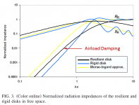
I had investigated the damping potential of closely spaced wires and/or low %OA(Open Area) perforated sheet stators…thought I had posted it years ago, but can’t seem to locate. In any case, you will need to get %OA < 20% before significant amounts of damping is seen, and then only if the holes or slots are quite small, something less than 0.02”. As an example, attached is measurement of a KLH Nine woofer that has roughly 10%OA. Still not much damping as the holes are about 0.1” diameter.
What does help with acoustic damping in hybrids is to increase the resonance frequency so it gets closer to the ka=1 point below which acoustic damping drops off like a rock…see attached pic of radiation impedance with the resistive damping curve pointed out. The ka=1 point is defined by the width of the ESL panel, roughly equal to the point where wavelength is the same size as width.
Attachments
Hello Steve,
As usual, you’ve provided another insightful gem to bookmark for future reference.
I had imagined that closer wire spacing might provide some damping as an added benefit, but the primary reason I targeted 42% open area was for efficiency.
Back in the 70’s, Panasonic Corp did some research on electrostatic tweeters which showed that the optimal (i.e. max acoustic output) open area was 42%. I don’t recall whether the data was limited to tweeter frequencies or was applicable to the full audio bandwidth, only that it was a graph showing open area percentage on one axis and SPL on the other axis.
I just did a Google search for that chart, but I didn’t find it-- I will keep looking and post it here if I find it.
Charlie
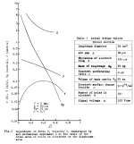
Was it perhaps the attached figure/table from this AES Convention/Journal article?
(Panasonic was one of the brand names Matsushita used in the 70s )
"Frequency Response Considerations for an Electrostatic Horn Tweeter Using Electret Elements,"
Publication: J. Audio Eng. Soc., vol. 24, no. 5, pp. 368-373, (1976 June.).
Authors: N. Sakamoto, T. Gotoh, N. Atoji, and T. Aoi,
Affiliation: ACOUSTIC RESEARCH LABORATORY, MATSUSHITA ELBCTRIC INDUSTRIAL CO. , LTD.
AES E-Library >> Frequency Response Considerations for an Electrostatic Horn Tweeter Using Electret Elements
AES E-Library >> Frequency Response of an Electrostatic Horn-Tweeter with Electret
Attachments
- Home
- Loudspeakers
- Planars & Exotics
- hybrid esl without resonance damping screens: possible?