After experimenting with building planar magnetic speaker, I have become increasingly intrigued with the idea with building an ESL. Specifically a full range one that doesn’t require a conventional woofer to produce decent bass. I’ve assembled a list of questions regarding such a speaker design:
What dimensions/area should I use for a panel that goes down to 50Hz?
What about the spacing between the Mylar and stators?
What bias voltage to use, how to generate it?
Turn ratio of audio transformers for stepping up the signal?
Best place to get the materials? Mylar, transformers, coating are the ones I’m mostly wondering about.
Lastly, for anyone who has built a full range ESL panel: what was the experience like? Are you satisfied with the sound quality?
Dimensions are going to be heavily influenced by your expected listening distance, SPL, and music. If your output requirements are modest (around 90 dB peak at listening position) and the distance is around 8 feet, something in the 16 inch by 48 inch range can get down to 50 Hz, but the panels and design need to be quite good for this level of performance at this size. Most people going for full-range output wind up building bigger panels than this. Looking at commercial designs and their reviews can give you an idea of the size range that's typically required for reasonable market acceptance and the real-world limitations. A few designs with Stereophile reviews: Quad ESL-63 and ESL-989, etc.; Martin Logan CLS; Audiostatic ES-100; Sound Lab A-1 and A-3.
Bias voltage is typically 50 volts per mil of diaphragm-to-stator spacing (1 mil = 0.001 inch).
Maximum peak-to-peak audio drive voltage should be twice the bias voltage (or a bit more, depending on your insulation). Your transformer and amplifier choices need to be made with this in mind.
I've built full-range panels. Getting OK performance is quite a bit easier than getting really good performance. I think I burned a mile of wire building various prototypes before I got reasonably happy with my last ones (Acoustat style panels). A lot of this was me covering ground on my own though, as DIY designs/advice weren't as readily available then. In general, a lot of trade-offs are involved with full-range ESLs. You need a more thorough understanding of the limits of the designs to pull them off vs. a midrange/treble panel.
Last edited:
Thanks for all the info. It’s amazing what information you can find if you dig deep enough.
How do you stretch a membrane that’s so large? Like 1’ by 5’ big?? Do you use a bicycle inner tube like many other diyers use? Or the heat gun method?
I’m wondering what the resonant frequency should be and how that corresponds to tension levels
How do you stretch a membrane that’s so large? Like 1’ by 5’ big?? Do you use a bicycle inner tube like many other diyers use? Or the heat gun method?
I’m wondering what the resonant frequency should be and how that corresponds to tension levels
Heat shrinking always seemed easiest to me, so that's what I did the vast majority of the time. I got a large supply of Mylar years ago, so my film and mounting method were consistent, which meant resonance was fairly predictable as well. A good temperature-controlled heat gun makes things a lot easier also.
There are equations to calculate resonance if you want to apply a specific tension. If you're heat shrinking, you can also work backward from a certain panel size/resonance and calculate the tension that way. You can get in the ballpark this way, but I typically wound up adjusting things because I was trying to get pretty specific results.
There are other mechanical ways to stretch diaphragms, but they're typically pretty involved.
Resonance is a decision point. Uncontrolled ESL resonance isn't really usable. The peak level and Q are both very high/unnatural.
You can use a single resonance below the intended frequency range and then filter it out so it's not excited.
You can also distribute the resonances across multiple frequencies within the intended range of the speaker, which helps if you want to use them to boost bass response. This is often not enough on its own to produce natural sound, though.
My most refined designs used multiple resonance frequencies and different kinds of damping to produce a more natural sounding low frequency range. If done carefully, you can maintain some of the bass boost while also not getting too aggressive with the damping and screwing up the midrange/treble.
Last edited:
Hi There !!!
May I Welcome You to this Wonderful Technology of ESL !!!
Here are just a few links to some links help get you started,
My current design methods,
Bookshelf/Desktop ESL's
and much much more,
Help, Advice, Information, Reassurance... ???
DIY electrostatic speakers for dummies
ESL High Voltage supply
A most excellent build using my stator coating methods,
High strength Dielectric Coatings, fact or fiction
First time ESL builder
First ESL build - Full Range .
Transformers,
ESL speaker build photos
Materials,
ESL Diaphragm material, Anyone tried different?
Amp design,
Isobaric ESL alternative
And the Very Most Important, Electrical Segmentation !!
Optimizing my DIY full range esl
I have complied several of these lists through the years, if there is anything that you don't understand here Please Do Not Be Afraid to Ask !!!
Cheers !!!

And, Enjoy !!!
jer
May I Welcome You to this Wonderful Technology of ESL !!!
Here are just a few links to some links help get you started,
My current design methods,
Bookshelf/Desktop ESL's
and much much more,
Help, Advice, Information, Reassurance... ???
DIY electrostatic speakers for dummies
ESL High Voltage supply
A most excellent build using my stator coating methods,
High strength Dielectric Coatings, fact or fiction
First time ESL builder
First ESL build - Full Range .
Transformers,
ESL speaker build photos
Materials,
ESL Diaphragm material, Anyone tried different?
Amp design,
Isobaric ESL alternative
And the Very Most Important, Electrical Segmentation !!
Optimizing my DIY full range esl
I have complied several of these lists through the years, if there is anything that you don't understand here Please Do Not Be Afraid to Ask !!!
Cheers !!!
And, Enjoy !!!
jer
Last edited:
Thanks for all the links! It’s really helpful for a beginner like me who’s wanting as much information as possible. After reading some of Roger Sanders’ book along with some forum posts I complied a list of specifications for the speaker I want to build:
Panel Shape: Flat
Electrically Segmented: No
Frequency Response: 50Hz-20kHz +/- 3dB
Size/Area: 60in tall by 15in wide, 6.25ft^2
DS Spacing: 1/16in
Bias Voltage: 6.25kV
Audio Voltage: 12.5kV pk-pk
Diaphragm: 3um mylar
Sensitivity: ~85dB
Stator Material: Perforated Steel, 1/8in holes, 40% open area
Insulating Spacers: 1/16in double sided foam tape
Frame: 1in thick MDF
First of all, let me know what you think of these specs and if they’re even achievable.
My main concern is diaphragm spacing, diagram tensioning and voltages:
What spacing should I use between the diaphragm and stator? I’m using foam tape as spacers but my only convenient choices are 1/8” and 1/16”.
It seems like heat shrinking the Mylar is the only practically method of tensioning for large panels. What are your thoughts? Is all Mylar suited for this?
Are commercially available HV generators any good? Where do I get audio grade transformers and what ratios should I use? Do I really need two per panel?
Your Welcome !!!
I have thought about rewriting that book several time but but This guy already did !!!
Frank Verwal,
His Most Excellent Info can be found here,
Elektrostatic Loudspeakers
jer
I have thought about rewriting that book several time but but This guy already did !!!
Frank Verwal,
His Most Excellent Info can be found here,
Elektrostatic Loudspeakers
jer
That is your basic recipe but there is a lot wrong with it.
#1
A 15" wide panel looks impressive but won't yield you the Best Performance without electrical segmentation and a panel that size will need at least 3" to 5" wide mechanical segment just to keep the diaphragm stable !
Even with that you will still have quite a narrow sweet spot due to the beaming of the high frequency's because of the large physical width.
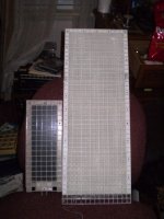
Just like these panels that some may recognize (below) !!!
The build is found right in the links as well.
These links show the whole process of CharlieM and Mavric building his panels and what is exactly involved in building a Perforated Metal ESL.
it is fairly easy actually, may I suggest though you choose a smaller size build as your first build, until you learn your style of technique of building these things.
I started out small with super super results and it took me 10 years to develop them. Now I am working on a 4th gen version and taking those techniques to the next level of building a much much larger system than my Desktop ESL version's.
new esl start to finish build
different ideas for ESL panels
new esl start to finish build
Material for ESL
However they Do Rock especially when set out side they hold there own extremely well, but not an optimal design, I had some say so in this design, but I was just learning a few things at the time myself as well, as too what causes the bad horizontal dispersion in the First place in ESL's !!
I didn't much care for the large segment spacing in the First place, I had suggested something in the 3-4 inch range but it is what Maveric choose to do here they are again in all of their Glory, well taken care of !!!
Still don't have em setup yet. :headbang:
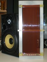
The large TIG stator will be the back stators of my larger ESL system in the making since 2006 I made 6 of those in the winter time with nothing to do, I still have to calculate and build the electrically segmented front stator pieces yet.
jer
P.S. More links here,
Newbe Question: ESL bias power supply
#1
A 15" wide panel looks impressive but won't yield you the Best Performance without electrical segmentation and a panel that size will need at least 3" to 5" wide mechanical segment just to keep the diaphragm stable !
Even with that you will still have quite a narrow sweet spot due to the beaming of the high frequency's because of the large physical width.
Just like these panels that some may recognize (below) !!!
The build is found right in the links as well.
These links show the whole process of CharlieM and Mavric building his panels and what is exactly involved in building a Perforated Metal ESL.
it is fairly easy actually, may I suggest though you choose a smaller size build as your first build, until you learn your style of technique of building these things.
I started out small with super super results and it took me 10 years to develop them. Now I am working on a 4th gen version and taking those techniques to the next level of building a much much larger system than my Desktop ESL version's.
new esl start to finish build
different ideas for ESL panels
new esl start to finish build
Material for ESL
However they Do Rock especially when set out side they hold there own extremely well, but not an optimal design, I had some say so in this design, but I was just learning a few things at the time myself as well, as too what causes the bad horizontal dispersion in the First place in ESL's !!
I didn't much care for the large segment spacing in the First place, I had suggested something in the 3-4 inch range but it is what Maveric choose to do here they are again in all of their Glory, well taken care of !!!
Still don't have em setup yet. :headbang:
The large TIG stator will be the back stators of my larger ESL system in the making since 2006 I made 6 of those in the winter time with nothing to do, I still have to calculate and build the electrically segmented front stator pieces yet.
jer
P.S. More links here,
Newbe Question: ESL bias power supply
Attachments
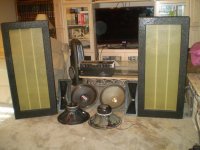
Well You see those panels of Mavric's up on the right?
Those panels are quite large so lets try and analyze and predict their performance a bit without going overboard as I really love these things for what they are !!!
Their history is in these threads and I finally will be able too have the time to test em up Proper too show everyone one what anybody can do if the really want it bad enough !!!
This Not about its flaws, if there are really any at all !!!
We'll find out when those tests come.
One of the transformers is messed up and it took out my Ashley FTX2000 amp so I been kinda pretty pissed off at them but I guess I got some fixin' to do!!!
More on that later !!
CharlieM and Mavric did a fabulous job on these things and I just wanted to test them out and get them back running so maybe Mavric will get a space soon for them and set them up for himself to enjoy again.
Cheers !!!!
Mavric and CharlieM !!
I just wanted to make it clear to everyone what the deal was with these things and why they made a 1100 mile trip to me just in case they were wondering,
Maveric didn't have the space for them for a minute and where he had them stored they almost got destroyed !!
As you can see I don't have the matching TL woofers that he created for them as well, those are long gone......... Water ! :/
So I promised Mavric, that I would take care of them and when he gets setup we'll get them back set up at his place again amps and all !!
So that is the history on their Fine Example of a DIY ESL and I will get to the details of what to expect of such a build in the next post.
jer
Here are my ideas to your project:
- Electrostatic powder coating of the stators with polymer resin
- Sharp edges of punched holes should be on the outside
- 3 um mylar is probably too thin
- Double sided foam tape has no defined thickness. And you will need to disassemble later on, for sure. I would use glass epoxy PCB strips.
- Hold the structure together using nylon screws and bolts
- Perhaps you don't need electrical segmentation, but you do need mechanical segmentation. I would divide the width to 3 sections (or maybe 2), each about 5" wide. You need support the diaphragm, otherwise it will stick to the stator. Or you have to stretch it more to prevent sticking to the stator, but then low frequency response will be poor. The QUAD ESL has 3 segments of 8 cm (slightly more than 3") on each bass panel.
- Mechanical stretching of the diaphragm is better than thermosetting (heat gun)
- You need dust covers (but they don't need to be segmented)
- I have been thinking about something similar surface to prevent rattling:
But the edges are curver vertically only a few millimeters (1/4" or so). It might also improve horizontal dispersion at higher frequencies.
- HV leaking paths are your biggest enemy
- Electrostatic powder coating of the stators with polymer resin
- Sharp edges of punched holes should be on the outside
- 3 um mylar is probably too thin
- Double sided foam tape has no defined thickness. And you will need to disassemble later on, for sure. I would use glass epoxy PCB strips.
- Hold the structure together using nylon screws and bolts
- Perhaps you don't need electrical segmentation, but you do need mechanical segmentation. I would divide the width to 3 sections (or maybe 2), each about 5" wide. You need support the diaphragm, otherwise it will stick to the stator. Or you have to stretch it more to prevent sticking to the stator, but then low frequency response will be poor. The QUAD ESL has 3 segments of 8 cm (slightly more than 3") on each bass panel.
- Mechanical stretching of the diaphragm is better than thermosetting (heat gun)
- You need dust covers (but they don't need to be segmented)
- I have been thinking about something similar surface to prevent rattling:
An externally hosted image should be here but it was not working when we last tested it.
or this:
An externally hosted image should be here but it was not working when we last tested it.
But the edges are curver vertically only a few millimeters (1/4" or so). It might also improve horizontal dispersion at higher frequencies.
- HV leaking paths are your biggest enemy
Panel Shape: Flat
Electrically Segmented: No
Frequency Response: 50Hz-20kHz +/- 3dB
Size/Area: 60in tall by 15in wide, 6.25ft^2
DS Spacing: 1/16in
Bias Voltage: 6.25kV
Audio Voltage: 12.5kV pk-pk
Diaphragm: 3um mylar
Sensitivity: ~85dB
Stator Material: Perforated Steel, 1/8in holes, 40% open area
Insulating Spacers: 1/16in double sided foam tape
. . .
My main concern is diaphragm spacing, diagram tensioning and voltages:
What spacing should I use between the diaphragm and stator? I’m using foam tape as spacers but my only convenient choices are 1/8” and 1/16”.
Are commercially available HV generators any good? Where do I get audio grade transformers and what ratios should I use? Do I really need two per panel?
- Electrostatic powder coating of the stators with polymer resin
. . .
- Double sided foam tape has no defined thickness. And you will need to disassemble later on, for sure. I would use glass epoxy PCB strips.
As you've probably figured out, there are a lot of details to work out once you dig into this. If you have no experience with ESLs and you aren't following someone else's exact building instructions, I suggest starting small and simple to refine your building methods. It's likely you'll make mistakes in the beginning. It's much easier and more gratifying to figure those things out quickly on panels you don't have much invested in.
Some specific things from previous posts:
If you aren't going to electrically segment, how are you going to equalize the panels? Sanders is one of the few designers that doesn't electrically segment. He has his reasons, but it's worth considering that most people go another direction. Acoustat also started off unsegmented, but switched with their Spectra series. Acoustats also used a two-transformer circuit to equalize frequency response. I don't remember seeing a DIYer try this method on their own though (other than using Acoustat interfaces on their own panels).
Bias and drive level for 1/16" (0.0625") diaphragm-to-stator spacing - your values are twice what they should be.
1/16" spacing for full range - it can be done, but you will have to adequately damp the resonance to use spacing this small or filter it out another way. You'll also need reasonable SPL expectations. Point of reference: the Quad ESL-63 used damping and spacing of approximately 0.1" with a system resonance around 40 Hz.
3M tapes have consistent thickness and you can trust them. They are more expensive, but if you pick the right one they work and you don't have to worry about them. If you watch a Martin Logan build video, you'll typically see the tartan pattern or 3M's logo on the tape's release liner. I went 3M early in my ESL experience and never had a desire to use anything else after that. Taking apart panels can be a challenge though. Good 2-sided tape is pretty impressive stuff.
It's very hard to design high step-up ratio transformers with wide bandwidth. Using two of them (or more) has advantages in a high ratio setup. The other approach is to use a very high powered amplifier to compensate for a low turns ratio. Both approaches are valid; it's a matter of your preference.
Perforated metal makes for a relatively fast build for early experiments, but longer term it's not a material I like. If you want to electrically segment, it's harder to deal with. If you want to insulate it also complicates things.
Insulated panels are my preference for a real build. When experimenting it can be left out (if you're careful and can keep from electrocuting yourself). Insulation in general can complicate things if you're not careful with material selection. Volume resistivity and dielectric constant have to be in the right ranges to keep the bias and drive voltages in the gap instead of across the insulation. If you do it wrong you'll need very high voltages and won't gain any real world performance for the extra voltage used. You can also have dielectric absorption, which causes wandering sensitivity after high drive levels. PVC and nylon are typical insulation types that have been successfully used with ESLs. If you get away from these, do your homework first.
Last edited:
Here are my ideas to your project:
- Electrostatic powder coating of the stators with polymer resin
- Sharp edges of punched holes should be on the outside
- 3 um mylar is probably too thin
- Double sided foam tape has no defined thickness. And you will need to disassemble later on, for sure. I would use glass epoxy PCB strips.
- Hold the structure together using nylon screws and bolts
- Perhaps you don't need electrical segmentation, but you do need mechanical segmentation. I would divide the width to 3 sections (or maybe 2), each about 5" wide. You need support the diaphragm, otherwise it will stick to the stator. Or you have to stretch it more to prevent sticking to the stator, but then low frequency response will be poor. The QUAD ESL has 3 segments of 8 cm (slightly more than 3") on each bass panel.
- Mechanical stretching of the diaphragm is better than thermosetting (heat gun)
- You need dust covers (but they don't need to be segmented)
- I have been thinking about something similar surface to prevent rattling:
or this:
But the edges are curver vertically only a few millimeters (1/4" or so). It might also improve horizontal dispersion at higher frequencies.
- HV leaking paths are your biggest enemy
Why is 3um mylar too thin? I read somewhere that soundlab uses it in their speakers because it has a better treble response
How do you do mechanical stretching for extremely large panels?
As you've probably figured out, there are a lot of details to work out once you dig into this. If you have no experience with ESLs and you aren't following someone else's exact building instructions, I suggest starting small and simple to refine your building methods. It's likely you'll make mistakes in the beginning. It's much easier and more gratifying to figure those things out quickly on panels you don't have much invested in.
Some specific things from previous posts:
If you aren't going to electrically segment, how are you going to equalize the panels? Sanders is one of the few designers that doesn't electrically segment. He has his reasons, but it's worth considering that most people go another direction. Acoustat also started off unsegmented, but switched with their Spectra series. Acoustats also used a two-transformer circuit to equalize frequency response. I don't remember seeing a DIYer try this method on their own though (other than using Acoustat interfaces on their own panels).
Bias and drive level for 1/16" (0.0625") diaphragm-to-stator spacing - your values are twice what they should be.
1/16" spacing for full range - it can be done, but you will have to adequately damp the resonance to use spacing this small or filter it out another way. You'll also need reasonable SPL expectations. Point of reference: the Quad ESL-63 used damping and spacing of approximately 0.1" with a system resonance around 40 Hz.
3M tapes have consistent thickness and you can trust them. They are more expensive, but if you pick the right one they work and you don't have to worry about them. If you watch a Martin Logan build video, you'll typically see the tartan pattern or 3M's logo on the tape's release liner. I went 3M early in my ESL experience and never had a desire to use anything else after that. Taking apart panels can be a challenge though. Good 2-sided tape is pretty impressive stuff.
It's very hard to design high step-up ratio transformers with wide bandwidth. Using two of them (or more) has advantages in a high ratio setup. The other approach is to use a very high powered amplifier to compensate for a low turns ratio. Both approaches are valid; it's a matter of your preference.
Perforated metal makes for a relatively fast build for early experiments, but longer term it's not a material I like. If you want to electrically segment, it's harder to deal with. If you want to insulate it also complicates things.
Insulated panels are my preference for a real build. When experimenting it can be left out (if you're careful and can keep from electrocuting yourself). Insulation in general can complicate things if you're not careful with material selection. Volume resistivity and dielectric constant have to be in the right ranges to keep the bias and drive voltages in the gap instead of across the insulation. If you do it wrong you'll need very high voltages and won't gain any real world performance for the extra voltage used. You can also have dielectric absorption, which causes wandering sensitivity after high drive levels. PVC and nylon are typical insulation types that have been successfully used with ESLs. If you get away from these, do your homework first.
How do you damp the resonance?
Do you mind linking me to some really good double sided tape?
How do you use two transformers per panel? How do you wire them up and what is the benefit versus using a high turn ratio?
Damping is accomplished by adding acoustic resistance to the panel. Depending on the amount you want, this can be layers of grille cloth, silk screen mesh, or felt of various thicknesses. A few links about damping:
Quad esl resonance damping: how?
https://www.diyaudio.com/forums/pla...-segmented-wire-stator-esl-7.html#post4188632
https://www.diyaudio.com/forums/pla...con-dots-resonance-control-3.html#post1958582
These are just a few of the tapes I've used successfully on normal plastics (Mylar, polycarbonate, rigid PVC like Sintra, etc.). There are others from 3M that will work also. If you haven't done it yet, downloading the large 3M double sided tape catalog is worth doing. They provide a lot of information and also get you thinking along the lines of classes of adhesives and carriers, which helps you figure out which tapes are likely to work for your application.
9485PC – acrylic adhesive, 0.005" thick, good for bonding diaphragms to plastic spacers
https://www.3m.com/3M/en_US/company...sfer-Tape-9485PC/?N=5002385+3293241558&rt=rud
4032 – acrylic adhesive, 0.032" thick, white open cell urethane foam carrier (other thicknesses available in this family) - used for spacers/diaphragm bonding
4965 – acrylic adhesive, 0.045" thick, black closed cell neoprene foam carrier - used for spacers/diaphragm bonding
https://multimedia.3m.com/mws/media/305674O/cintas-de-espuma-con-adhesivo-por-los-dos-lados.PDF
Some links about transformer configurations below. While these mostly deal with midrange/treble applications, the same ideas can be used for full-range designs. The Quad ESL-63 uses 2 transformers to achieve a 1:245 ratio. You won't normally find audio transformers with such high ratios, which is another benefit of using multiple transformers: it lets you get to higher ratios with more common transformers.
https://www.diyaudio.com/forums/pla...7-esl-transformer-question-2.html#post3718458
esl transformer.
Great site about the theory of ESLs:
Elektrostatic Loudspeakers
It was made by a former colleague of mine, after he made his own full-range ESLs.
Elektrostatic Loudspeakers
It was made by a former colleague of mine, after he made his own full-range ESLs.
.25mil mylar (6um) is generally what you want to use for any most any design up to about 6" sectional width anything wider you want to maybe go with a .5mil (6um) thickness.
I have some here that I have been saving and using since 1989 when I got it cheap from the back of a Popular Mechanics Magazine.
It is 12" in width and I have used it on my 8 1/2" wide panels as pictured in the First photo in post #8.
I can tell you First Hand that it took some work to get enough tension on it to keep that diaphragm stable without it sucking in to a stator on a low note transient signal or especially when a note hit its resonant frequency, it would get stuck every time!!!
I never had a method of using mechanical stretching methods except from taping it down to some glass, I have always just used the heat method, it works quick and gives me best consistency per panel for me at this time, one day I will build a stretcher because I know I am gonna need one as well, soon.
Also, Thank You MattStat for popping in on this as well as Icsaszar with your list, pretty much everything in it is good and I have too agree with MattStat as well, You hit those not exactly little details right on the money there !!
I wanted to mention a little something more about Mechanical sectioning as that was what the last question was, I won't go to deep with it but what it means that even though you may have a huge panel and surface area is one piece of mylar, sometimes you have to mechanically section it off in to smaller free moving areas in the total diaphragm area in order to keep it stable.
As MattStat mentioned there are many many ways to go about this and there are just as many threads to read on the subject as well as there are solutions that work.
It just all depends on Your needs and the way you decide to build Your system !!!
But,
One must understand the relationship between the panels dimensions and the reason why it performs the way it does.
It is because of them and how they are applied in to a working unit and make it what it is.
Sure anyone can throw together some stuff and make working panel it is that easy, really!!
But to make it sound right you need to think about a few rules as you go along in your design.
Nobody ever came right out and told me this stuff like I am doing now, it took me years to figure it out on my own and it is so simple it still kills me to this day at how simple this understanding can be.
Here It is,
When the signals 1/2 wavelength of the frequency being produced equals the width of the panel, then the radiation pattern will a Figure 8 Doublet pattern then starts to transition in to a more focused beam in the horizontal field as the frequency is raised.
And, As it is raised more little Lobes and beams start to form as well at different angles off to the sides of the centerline perpendicular to the panels orientation.
When you sit in front of a set of ESL that are too wide you get to sit in one spot with you head locked in one position and any movement at all from your head will crush and destroy your listening experience.
You may know this or have read about it and it is true and quite annoying if it is not compensated for properly or dealt with.
Directly off to the side you should here nothing as the front and back is canceled but as you go around the panel you will hear these lobes popping in and out.
Now this little rule is true for all driver's of all types not just Planars and Dipoles.
But, It is extremely noticeable when it comes to Dipole Configured sound systems.
The above rule is also used to help determine your low frequency performance as well and were your Dipole predicted cancellations are supposed to take effect.
Don't worry we have tons of Calculators and Spreadsheets for that stuff, I'll get all of those together a little later and put them all in one big little zip file, Everything here is found in these threads in some place or another
Now that you know this little rule it should give you a whole different perspective on how to go about choosing the size, Dimension and How and why some are made a certain way and how they are to be placed in your listening room.
Even as Quite as Simple as it is, It mean't GOLD to me and shined a whole lot of light on an annoying subject that I was hearing and couldn't understand !!
Why, where the smaller panels so much more appealing in their sound yet they are smaller, Way Smaller!???
In the way I was hearing the sound it was more open sounding and the stereo image stayed consistent for the most part even when I had to look around for a second!
No More head In A Vise Syndrome!!
Well it took me 7 years to find that answer and understand why since that day in 2003 !!!
jer
P.S Frank Verwaal's book explains all that sectioning stuff and why to a Tee.
Last edited:
In my Transformer tests I have found that even though it seems to be a waste in gains from maybe only a little bit to nothing in the step-up ratio, using 4 cores instead of using 2 as per current DIY methods however does put more inductance in to the Primary circuit for the amplifier.
If all of the cores and windings are the same then this raises the overall impedance curve up by 40% (1.414 the sqrt. of 2) with a doubling of ratio (IIRC) over the whole bandwidth.
I may have my numbers mixed up as I am just spurting this off of the top of my head of test data of 8 years ago. I will verify all this with new tests as at a future date in time.
I don't have that one documented here it was on my other website that is now defunct.
I plan on maybe re-doing another thread on transformers so that I can finally try a present some DIY recipes I had been working on in the last 8 years of me not posting anything on the subject.
I took a long break and I needed it and now I'm back with a fresh mind to start were I left off in 2013 and maybe show some ways drive these things and to either Make or Break Away from that Big Iron !!
jer
I apologize for the mistakes in my above posts but it was late I had already been typing all day, my Keyboard is wore out, and I really need to get my glasses replaced !!!
So I didn't finish,
As the frequency gets lowered from the width's 1/2 wavelength value, the wavefronts shape starts to change from its figure 8 doublet pattern form in to a completely circular omni-directional pattern that low frequency's are generally known for.
Only these are Dipole speakers and they act on a given space differently than a Monopole speaker does, not going there right now, there are many other places to read up on the subject.
Okay now that we know a little about how and why the is sound is made and how the shape of its wavefront is related to the panels width, for large width panels this becomes a problem as explained..................
By now you are saying to yourself,
" How is this issue dealt with and what is this equalization I am reading about now, I saw all of the videos its you just take two plates with holes in it and paint the crap out of em, hit em with some sticky tape and stretch some mylar on it an spray down with some GoD Awful Expensive stuff in a little spray can and stick the other plate on top and I am good to go right? ..................
And now you Talkin' Tuning and EQ!!!, OMG Man!!! ...... They Are Hermetically Sealed With Holes !!! " . :headbang:
Well there Are, Thankfully, Several Ways to go about this and this is where you get to make your decision as to how much work you wish to create for yourself and just how much space you are allowed to take up for your LITTLE project !!! He,he,he,he.
There is a very very simple equation to learn ( and I can't recall it!! ) that I post somewhere that gives you your angle of horizontal dispersion as per width of the driver and frequency produced, this will help you to map out your panels size requirements in your room.
For narrower panels of say no more than 12" but say more in to the 8-6 widths down to 3" or smaller width's like my Desktop models you can get a way with just a simple 12db sloped filter as normally used in most DIY builds and still not have too bad of an issue with head lock syndrome.
However all this eq'ing does is attenuate the high end so that the system appears to sound flat and not overly bright, but, you still have the issue of losing some or all of your high end as soon as your listening position goes just ever so slightly off the center of the panel position.
Martin Logan still uses this method and companies like Quad used this method in a W-T-W configuration using two different width panel sizes in their ESL57 model.
This is generally done with some sort of active filtering in the line before the amp.
Or, even sometimes just adding some resistance to the primary winding of the step-up transformer is enough the tame the High End peak and the Transformers High Frequency Resonant Peak (caused by the total system capacitance and the transformers leakage inductance) too.
For large widths and giant width panels if you choose this route, need to be planned out for sure ,This were planning your Mechanical segmentation comes in to play, if it is to be used.
As I mentioned Mavric's panel's are Wide !!
The open area width is 15" with 14" being the active area by about 48" long with 3 mechanically separate sections (IE: Segment's) that are approximately 4.5" wide as measured.
A 4.5" wide segment is not so bad now that I have measured them, they just looked much larger than that.
Anyhow all of the same rules apply for dispersion here as per segment as a single panel design would be with the very same dimensions, only now the sweet spot of the system has been widen as a whole plus your normal dispersion angle off to the sides accounted from the centers of the end segments of the panel.
Yes this does produce a little bit more of smearing of the image in general compared to that of one single segment or open panel, but it is far less of an effect IMHO compared to making Curve Shaped Stators.
I have a friend in these threads that did such a build, he is not far from me and hopefully I may be able to get out of here this summer and go check them out for the First time.
Anyhow last time I did an accurate calculation each panel was the equivalent displacement 3x12's or 2x15's or something,
So, They will produce some bass!!
But with the D/S limited to 1/16" or so makes it very limited for full range use.
Maveric's panels were designed to be used at about 400hz and above and with a TL woofer for the low end, this is your Classic DIY'er build and it works Well, Very well indeed, I am very very thrilled to have them for a minute.
We also used a special coating on those panels, They are Rhino Coated Stators !!!
More on that later!!
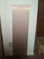
Another Friend I have here Dochungwell produces a few panels here and there for friends and such, His design is another Very Elegant Looking simple single approx 12'-14"x 48" panel design done right !!
Then you have CharlieM's impeccable Electrically Segmented wide diaphragm design.
The diaphragm is one huge sheet as you can imagine with no restraints of displacement and nor is it broken up in to smaller Segments for the most part.
That My Friend is the Cream of the Crop of Full Range Large Diaphragm ESL Design Right there !!!
And I am so glad that I talked Charlie in to trying this method a long time ago !!
As much as I would like too, I am not going in to the details of how electrical segmentation works as there are several threads on just that one subject alone as well as how to go about install and use the ESL_SEG_UI program we found and posted in those threads.
And Finally but not the least.
There are some companies that use all the methods above at once, mechanical and electrical segmentation !!
A few such examples are Acoustats with two bass panels and one panel with 2 or 3 wire stator electrically separated segments for the high end.
And Who could forget the ESL 63's where the whole panel area is made of of smaller sized panels and each one of those panels hass an an etched circular pattern of a electrically segment ring stator on PCB material in order to try and produce a true spherical wavefront shape for all of the frequency's across the Whole Audio Bandwidth of the driver.
Hopefully this will get you started at what factors are actually more important than others when planning your Full Range ESL systems.
It is a lot to swallow at once so take your time study it and plan it out !!
As I had mentioned and others have it is best to start out small to just to get a feel of the construction methods and any failures hopefully won't be to costly to start over if needed.
Because, Yes, There is gonna be some thing that will go wrong and set you back a minute.
It never fails !!
I have seen it every time with a new builder, I know I was once there too myself !!!
Overlooking something and scorched the coating or whatever and have to either throw it out and get a new piece(Expensive!!).................................
Or, Try and salvage the old piece, and 9 times out 10 it isn't worth all the time and money to strip it down and start over with it just to watch it fail again, and then do it right all over again over a simple mistake !!
Been There, Done That, Read about it in those threads, But it is what I call FUN!! He,he,he,he
jer
So I didn't finish,
As the frequency gets lowered from the width's 1/2 wavelength value, the wavefronts shape starts to change from its figure 8 doublet pattern form in to a completely circular omni-directional pattern that low frequency's are generally known for.
Only these are Dipole speakers and they act on a given space differently than a Monopole speaker does, not going there right now, there are many other places to read up on the subject.
Okay now that we know a little about how and why the is sound is made and how the shape of its wavefront is related to the panels width, for large width panels this becomes a problem as explained..................
By now you are saying to yourself,
" How is this issue dealt with and what is this equalization I am reading about now, I saw all of the videos its you just take two plates with holes in it and paint the crap out of em, hit em with some sticky tape and stretch some mylar on it an spray down with some GoD Awful Expensive stuff in a little spray can and stick the other plate on top and I am good to go right? ..................
And now you Talkin' Tuning and EQ!!!, OMG Man!!! ...... They Are Hermetically Sealed With Holes !!! " .
:headbang:Well there Are, Thankfully, Several Ways to go about this and this is where you get to make your decision as to how much work you wish to create for yourself and just how much space you are allowed to take up for your LITTLE project !!!
He,he,he,he. There is a very very simple equation to learn ( and I can't recall it!! ) that I post somewhere that gives you your angle of horizontal dispersion as per width of the driver and frequency produced, this will help you to map out your panels size requirements in your room.
For narrower panels of say no more than 12" but say more in to the 8-6 widths down to 3" or smaller width's like my Desktop models you can get a way with just a simple 12db sloped filter as normally used in most DIY builds and still not have too bad of an issue with head lock syndrome.
However all this eq'ing does is attenuate the high end so that the system appears to sound flat and not overly bright, but, you still have the issue of losing some or all of your high end as soon as your listening position goes just ever so slightly off the center of the panel position.
Martin Logan still uses this method and companies like Quad used this method in a W-T-W configuration using two different width panel sizes in their ESL57 model.
This is generally done with some sort of active filtering in the line before the amp.
Or, even sometimes just adding some resistance to the primary winding of the step-up transformer is enough the tame the High End peak and the Transformers High Frequency Resonant Peak (caused by the total system capacitance and the transformers leakage inductance) too.
For large widths and giant width panels if you choose this route, need to be planned out for sure ,This were planning your Mechanical segmentation comes in to play, if it is to be used.
As I mentioned Mavric's panel's are Wide !!
The open area width is 15" with 14" being the active area by about 48" long with 3 mechanically separate sections (IE: Segment's) that are approximately 4.5" wide as measured.
A 4.5" wide segment is not so bad now that I have measured them, they just looked much larger than that.
Anyhow all of the same rules apply for dispersion here as per segment as a single panel design would be with the very same dimensions, only now the sweet spot of the system has been widen as a whole plus your normal dispersion angle off to the sides accounted from the centers of the end segments of the panel.
Yes this does produce a little bit more of smearing of the image in general compared to that of one single segment or open panel, but it is far less of an effect IMHO compared to making Curve Shaped Stators.
I have a friend in these threads that did such a build, he is not far from me and hopefully I may be able to get out of here this summer and go check them out for the First time.
Anyhow last time I did an accurate calculation each panel was the equivalent displacement 3x12's or 2x15's or something,
So, They will produce some bass!!
But with the D/S limited to 1/16" or so makes it very limited for full range use.
Maveric's panels were designed to be used at about 400hz and above and with a TL woofer for the low end, this is your Classic DIY'er build and it works Well, Very well indeed, I am very very thrilled to have them for a minute.
We also used a special coating on those panels, They are Rhino Coated Stators !!!
More on that later!!
Another Friend I have here Dochungwell produces a few panels here and there for friends and such, His design is another Very Elegant Looking simple single approx 12'-14"x 48" panel design done right !!
Then you have CharlieM's impeccable Electrically Segmented wide diaphragm design.
The diaphragm is one huge sheet as you can imagine with no restraints of displacement and nor is it broken up in to smaller Segments for the most part.
That My Friend is the Cream of the Crop of Full Range Large Diaphragm ESL Design Right there !!!
And I am so glad that I talked Charlie in to trying this method a long time ago !!
As much as I would like too, I am not going in to the details of how electrical segmentation works as there are several threads on just that one subject alone as well as how to go about install and use the ESL_SEG_UI program we found and posted in those threads.
And Finally but not the least.
There are some companies that use all the methods above at once, mechanical and electrical segmentation !!
A few such examples are Acoustats with two bass panels and one panel with 2 or 3 wire stator electrically separated segments for the high end.
And Who could forget the ESL 63's where the whole panel area is made of of smaller sized panels and each one of those panels hass an an etched circular pattern of a electrically segment ring stator on PCB material in order to try and produce a true spherical wavefront shape for all of the frequency's across the Whole Audio Bandwidth of the driver.
Hopefully this will get you started at what factors are actually more important than others when planning your Full Range ESL systems.
It is a lot to swallow at once so take your time study it and plan it out !!
As I had mentioned and others have it is best to start out small to just to get a feel of the construction methods and any failures hopefully won't be to costly to start over if needed.
Because, Yes, There is gonna be some thing that will go wrong and set you back a minute.
It never fails !!
I have seen it every time with a new builder, I know I was once there too myself !!!
Overlooking something and scorched the coating or whatever and have to either throw it out and get a new piece(Expensive!!).................................
Or, Try and salvage the old piece, and 9 times out 10 it isn't worth all the time and money to strip it down and start over with it just to watch it fail again, and then do it right all over again over a simple mistake !!
Been There, Done That, Read about it in those threads, But it is what I call FUN!! He,he,he,he
jer
Last edited:
Okay so you Still want to build a Giant (or Small) Full Range ESL?!!!
How Do You Plan On Driving that thing??
You have to ask yourself, "What does it take to get in to the lowend ?", Ya lots of surface area gets you there plus displacement, " But then what allows them to get so low and so clean ?!!! " ....................
Big Expensive Iron..............
That is the only way !!!
Or, Eventually learn HV amplifier circuitry and go the DD amp route
Some manufacture's like "Martin Logan" and maybe Quad not sure, go as far as using multiple compounded diaphragms (isobaric style) to gain more authoritive control at the super low frequency end of the spectrum some (ML) use a separate bass panel with a smaller width semi-fullrange panel
Well, That is about all I have on this without going in to actual construction tips, But at least this gives you somethings to look at when you are deciding how to go about doing your build.
Anything you decide we can help you.
Once you get there, Please!!! ..... Feel Free, to pop in here and Ask if you have any Questions at all about anything DIY ESL !!
We/I never get bored seeing Newcomers jump in to the world of DIY ESL's and succeed with their Own creation !!
Cheers and Good Luck !!!
jer
- Home
- Loudspeakers
- Planars & Exotics
- Tips on building full range ESLs