No, they are not big.Wow! These are very big speakers!
Thanks for sharing.
The woofers are "tuned" to 40 Hz and the subwoofers to 20 Hz.
Then the cabinets must be those sizes.
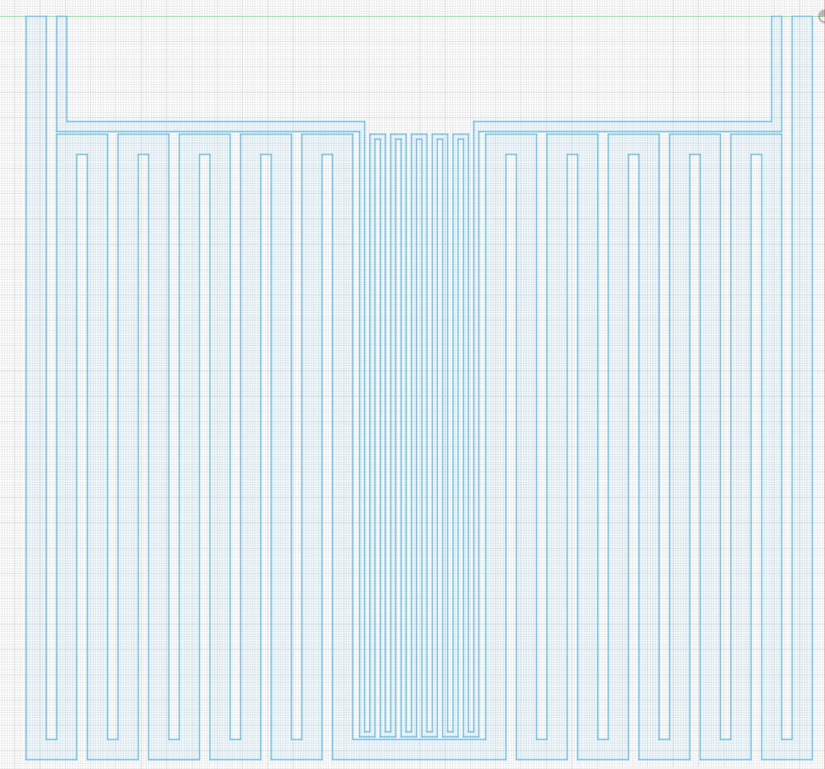
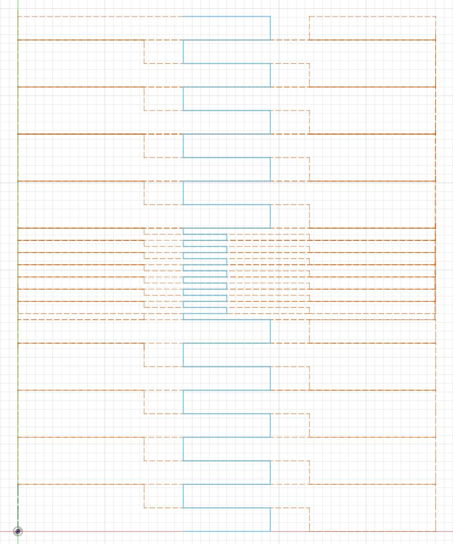
My first shot at the SALS?A! membrane:
It'll be 247 mm high and 60 mm wide.
The tweeter will be 10 mm wide when folded and the two middles will be 25 mm each.
It will take nine MTM membranes for the complete speaker.
I will add fillets before I cut but are there any other things to consider?
An externally hosted image should be here but it was not working when we last tested it.
It'll be 247 mm high and 60 mm wide.
The tweeter will be 10 mm wide when folded and the two middles will be 25 mm each.
It will take nine MTM membranes for the complete speaker.
I will add fillets before I cut but are there any other things to consider?
Last edited:
Yes, they might.The middles might have a low resistance. How wide are the traces?
Bernt
The traces are now 8 mm, but I think that I can reduce it to 6 mm if the resistance isn't high enough.
I was also thinking of reducing the width of the horizontal traces to perhaps 4 mm.
It'll be less efficient, but the sound producing part can be made higher.
Good idea! It is far better than adding some silicone.You could add a 30 µm self-adhesive alutape on the "backside" of the diaphragm on the center of height to stabilize the folded diaphragm.
Bernt
I didn't need it on the SLAM! membrane though and they where even higher.
I will try to cut this tomorrow, then I'll now the way forward.
I moved the tweeter terminals inward a little bit to the location they will be when folded.
As I am nowadays using Fusion360 instead of the Silhouette CAD software, it was really easy to add the fillets:
I then export the sketch as dxf and then import it into the Silhouette CAD software.
Note that the size will not be correct.
It is not an inch/mm problem solely. Just multiply with 2.54 doesn't get the correct size. You'll have to scale it to the size the Fusion360 sketch has.
Anyway, I cut two membranes.
One with a 10 μm aluminium foil and one with 7 μm:
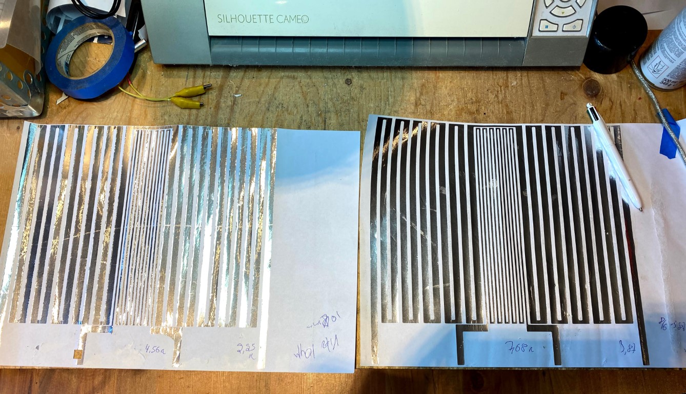
With the 10 μm foil, the tweeter is okay with 4.6 ohm but the mid is too low with 2.3 ohm.
With the 7 μm foil, the tweeter has 7.7 ohm and the mid has 3.9 ohm.
As the membrane sections will be series coupled by three and three and then parallel coupled (Or vice versa, as there's no inductance to consider I'll see what results in the best cabling), the actual resistance will go up a little due to the cabling.
So the nominal resistance will be 8 ohms for the tweeter and 4 ohm for the mid.
As I am nowadays using Fusion360 instead of the Silhouette CAD software, it was really easy to add the fillets:
An externally hosted image should be here but it was not working when we last tested it.
I then export the sketch as dxf and then import it into the Silhouette CAD software.
Note that the size will not be correct.
It is not an inch/mm problem solely. Just multiply with 2.54 doesn't get the correct size. You'll have to scale it to the size the Fusion360 sketch has.
Anyway, I cut two membranes.
One with a 10 μm aluminium foil and one with 7 μm:
With the 10 μm foil, the tweeter is okay with 4.6 ohm but the mid is too low with 2.3 ohm.
With the 7 μm foil, the tweeter has 7.7 ohm and the mid has 3.9 ohm.
As the membrane sections will be series coupled by three and three and then parallel coupled (Or vice versa, as there's no inductance to consider I'll see what results in the best cabling), the actual resistance will go up a little due to the cabling.
So the nominal resistance will be 8 ohms for the tweeter and 4 ohm for the mid.
Last edited:
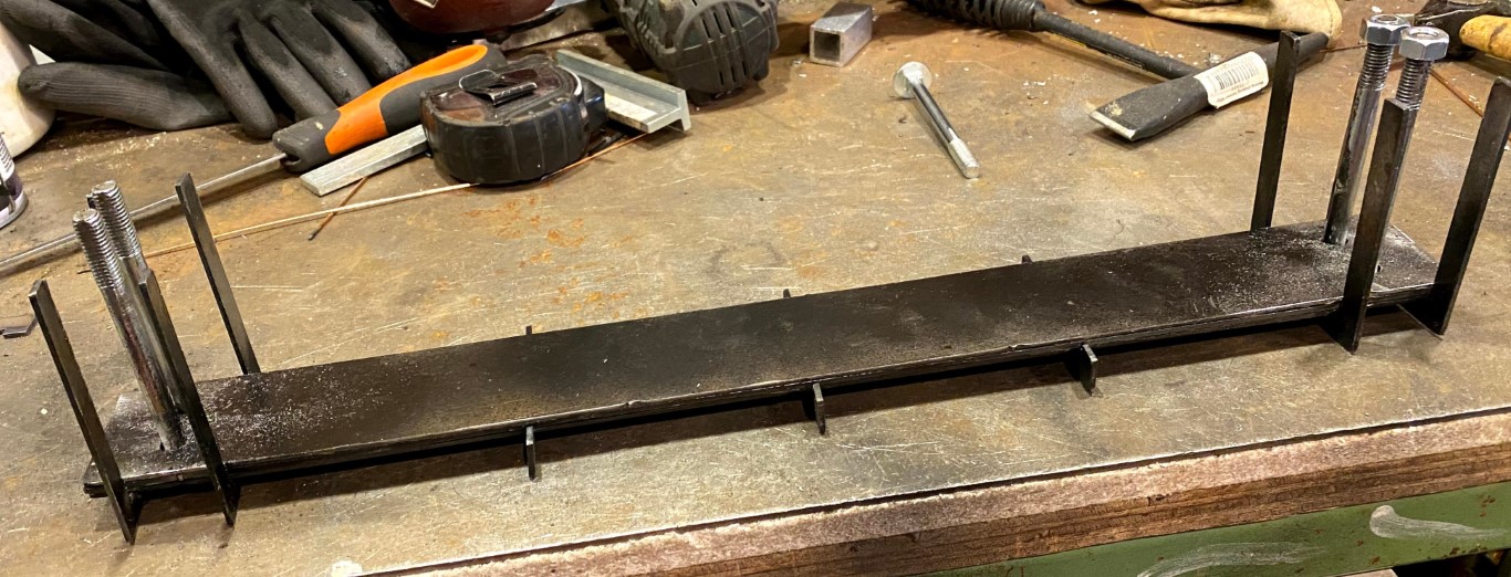
I welded it together. Not very polished, but it'll do the job:
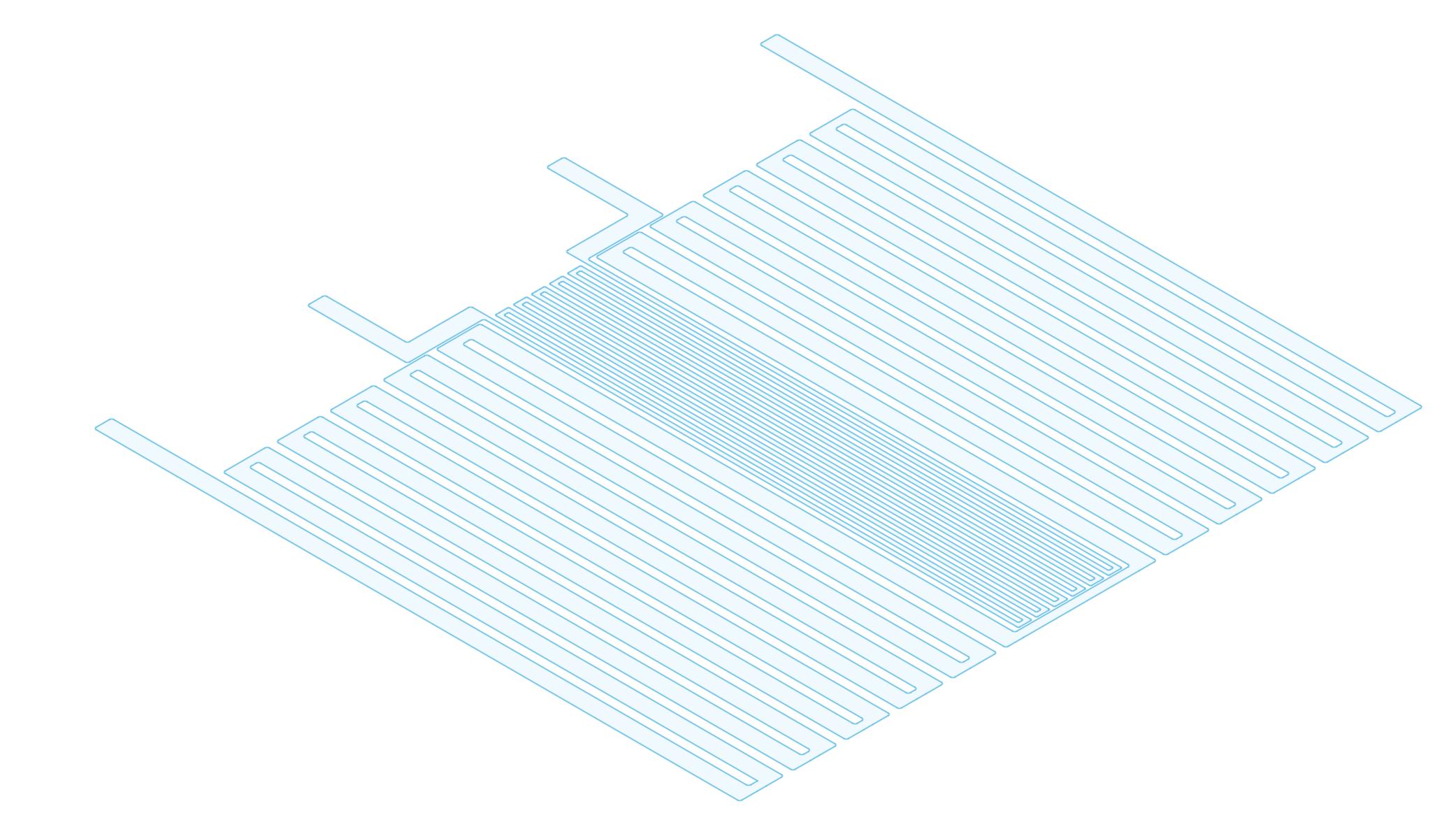
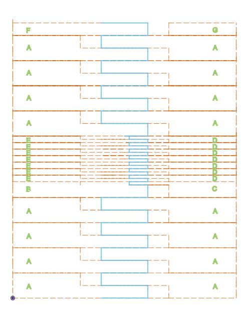
And this is how the membrane will be folded:
As you can see will the tweeter be phase inversed. But I'll solve with the cabling.
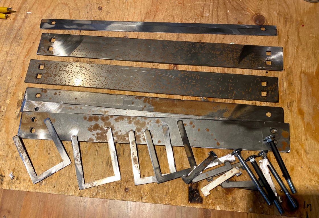
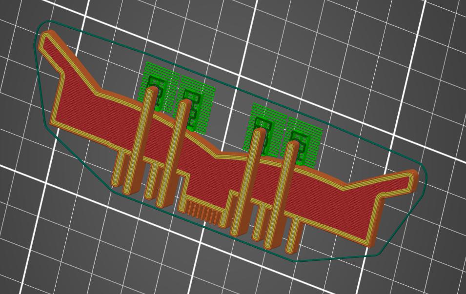
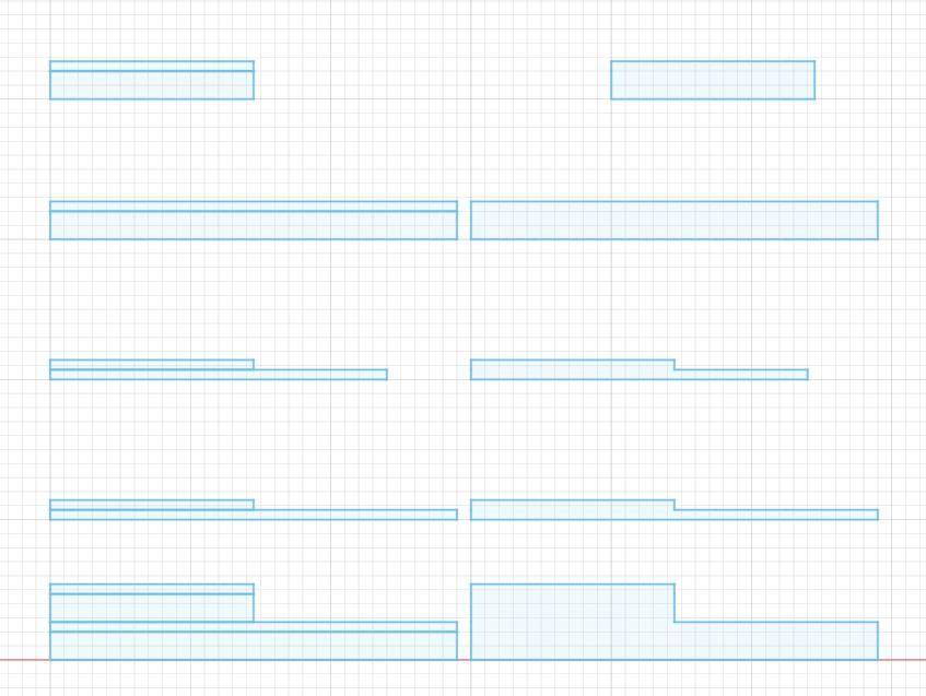
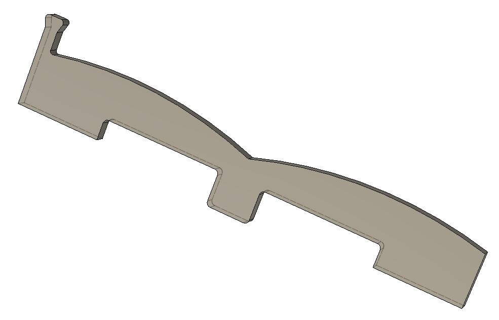
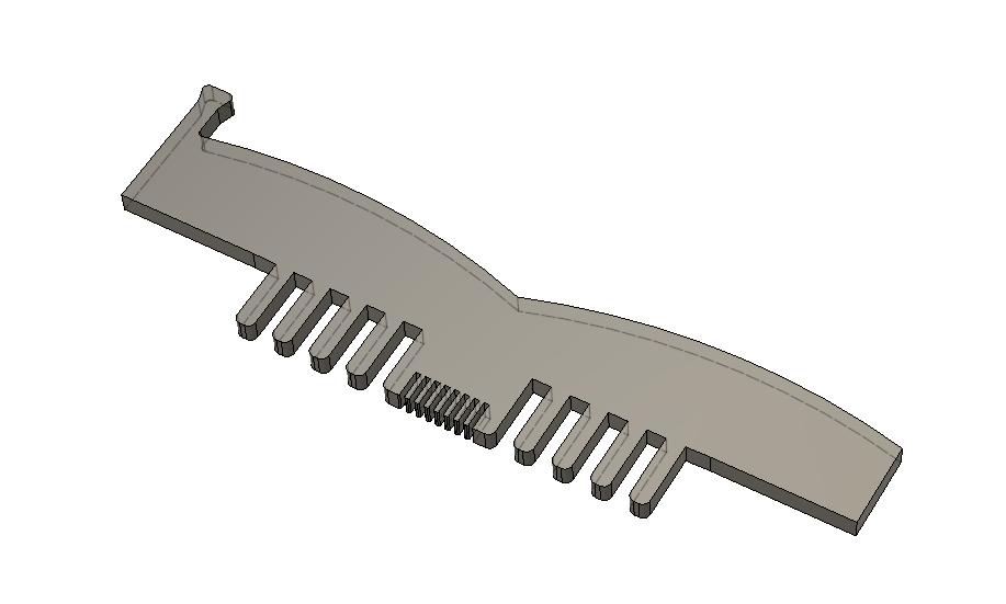
The different battens will look like this (composite to the right):
They will be cut out of 2 mm thick aluminium and 0.7 steel and glued together with VHB (100MP) to form complete battens.
And this is how the membrane will be folded:
An externally hosted image should be here but it was not working when we last tested it.
As you can see will the tweeter be phase inversed. But I'll solve with the cabling.
The different battens will look like this (composite to the right):
An externally hosted image should be here but it was not working when we last tested it.
They will be cut out of 2 mm thick aluminium and 0.7 steel and glued together with VHB (100MP) to form complete battens.
Yes, it comes in handy many times.Impressive cutting, and DIY plasma CNC cutter.
Bernt
For instance when cutting the pole pieces.
Especially the back pole pieces; they will have a handle to be able to pull them out easier and also an extension where the tweeter is.
The latter will make the reflected wave to have a higher frequency.
The M8 screws in the tool are only threaded at the top.Why are the holes square ?
The stem is actually 7 mm.
(I should really have shouldered screws. But when I discovered my mistake, I already had welded the screws to the tool.)
If the holes is 8 mm in diameter, there will be some extensive clearance when the battens has passed the threads.
So I partially grinded the threads to a 7 mm flat shape on two sides.
That way, I can use M8 screws to secure the tool when baking the membrane.
To make it easier to slide down the battens, I made the holes 7x10 mm instead of 7x8 mm
It doesn't matter if there is clearance in 10 mm direction.
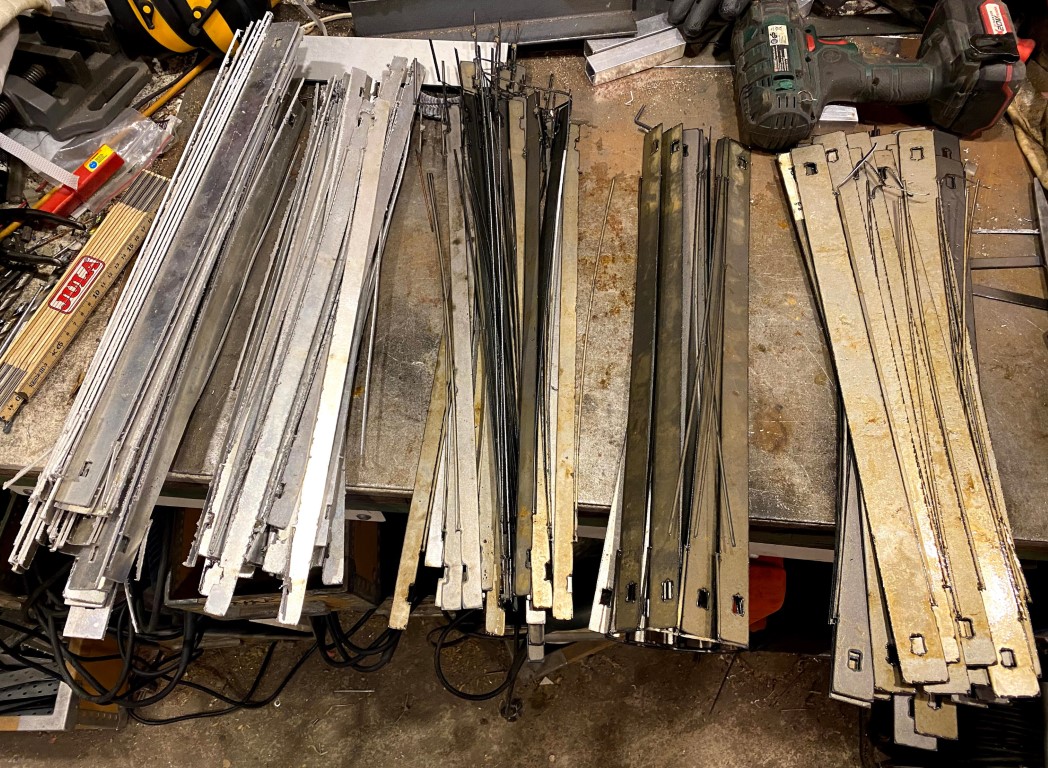
There's no twisting or warping. The steel/aluminium is cooled enough by the waterbath.Are the battens twisted due heat ? Seams quite flat
I also have placed tabs along one side, mostly to hinder a cut out part to get in the way for the subsequent plasma cuts.
An externally hosted image should be here but it was not working when we last tested it.
snip
Especially the back pole pieces; they will have a handle to be able to pull them out easier and also an extension where the tweeter is.
The latter will make the reflected wave to have a higher frequency.
snip
Like this:
An externally hosted image should be here but it was not working when we last tested it.
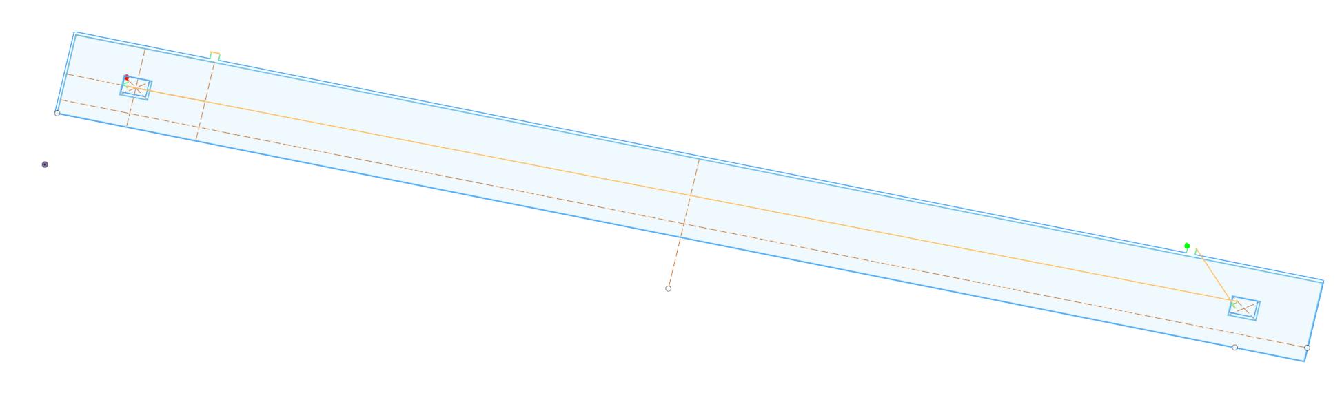
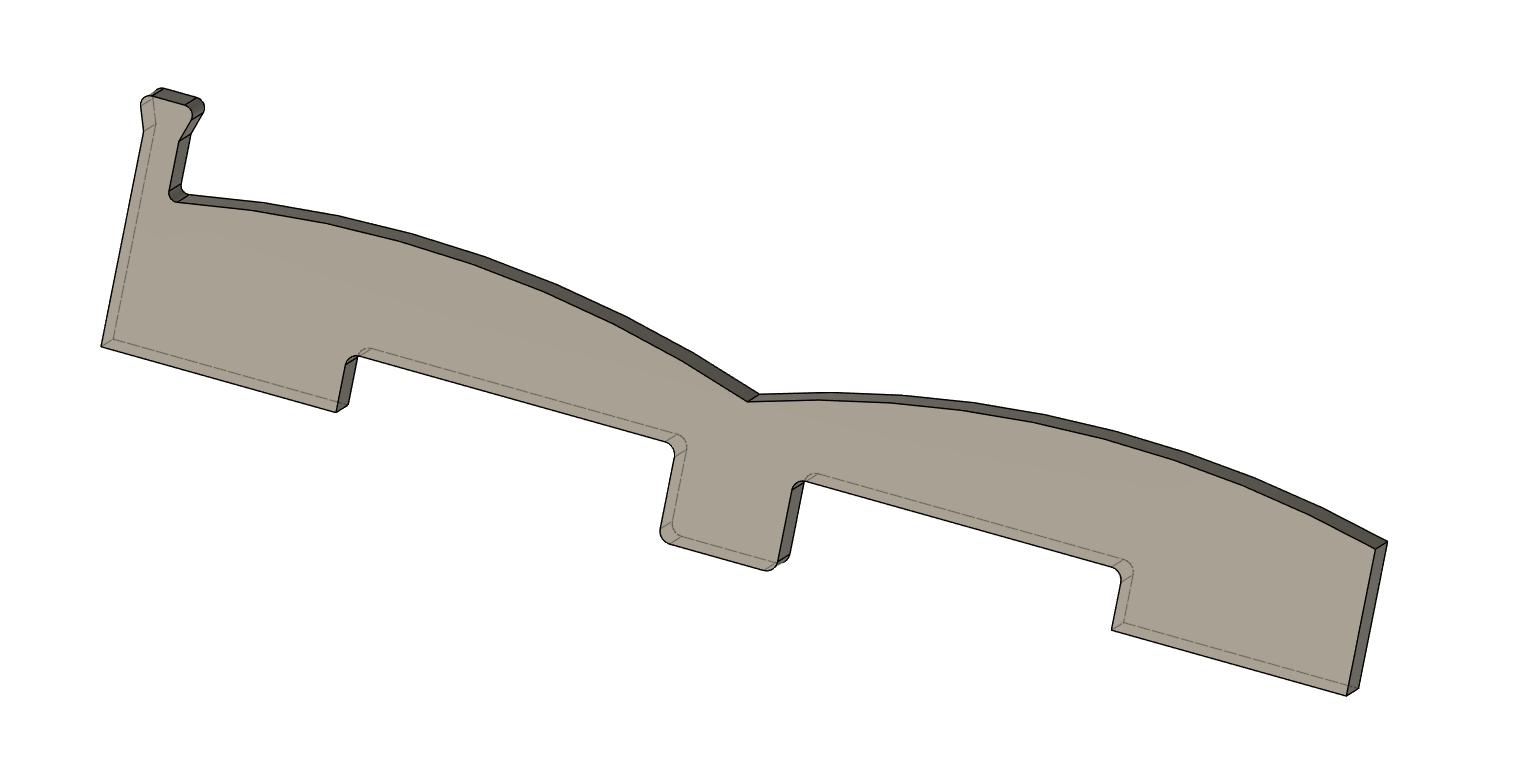
I made from the back pole piece:
and the path of the membran through the folding tool:
a membrane retainer:
The idea is that it replaces a back pole piece.
I will also make room for the terminals, they are quite fragile.
An externally hosted image should be here but it was not working when we last tested it.
and the path of the membran through the folding tool:
An externally hosted image should be here but it was not working when we last tested it.
a membrane retainer:
An externally hosted image should be here but it was not working when we last tested it.
The idea is that it replaces a back pole piece.
I will also make room for the terminals, they are quite fragile.
And this is how it looks with an experimental membrane, terminals and horizontal foils are missing.
From behind, the way it will be mounted:
Front view:
Close up:
It was a little bit tricky to mount the tweeter part, but I just had to concentrate.
This will be good.
From behind, the way it will be mounted:
Front view:
Close up:
It was a little bit tricky to mount the tweeter part, but I just had to concentrate.
This will be good.
Last edited:
Wow
You are too wild.
Are theese 3D printed?
I use clear silicone ,acid free, alcoholbased, to glue the ends.
Bernt
Wild? I would say inspired.
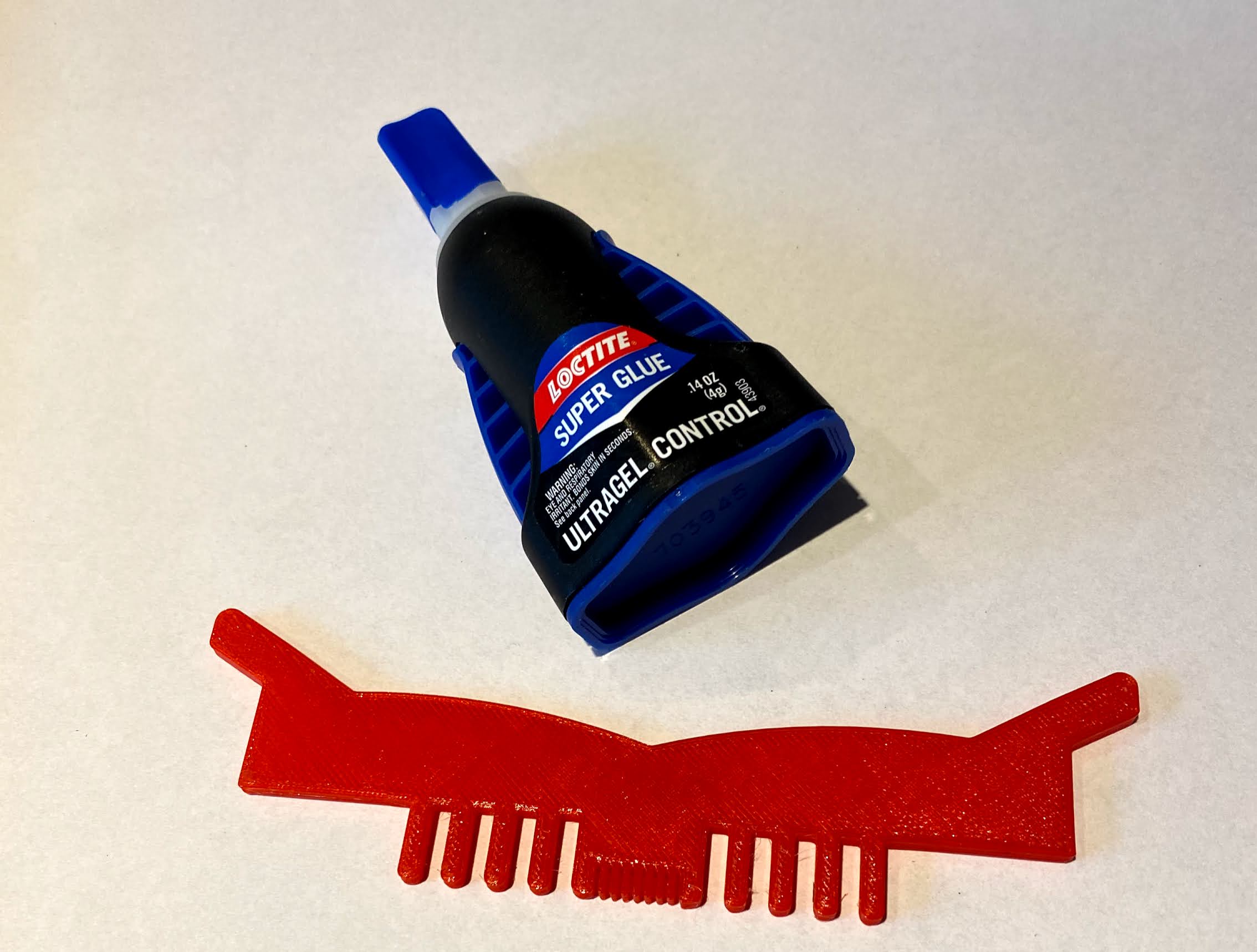
Yes, they are 3D printed.
I have now evolved them a little bit.
I though I'd try the glue in the picture below.
It's easy to apply in tight places and sticks really well and cures fast.
I might use silicone for gluing the membrane side to the magnets once the membrane is in the speaker though.
I am now building a mounting tool for gluing the membrane to the retainers.
BTW, one membrane takes one hour to make.
While it is in the oven, I can make another.
So I guess that I can make eight membranes in a working day.
Yes, it comes in handy many times.
For instance when cutting the pole pieces.
Especially the back pole pieces; they will have a handle to be able to pull them out easier and also an extension where the tweeter is.
The latter will make the reflected wave to have a higher frequency.
The M8 screws in the tool are only threaded at the top.
The stem is actually 7 mm.
(I should really have shouldered screws. But when I discovered my mistake, I already had welded the screws to the tool.)
If the holes is 8 mm in diameter, there will be some extensive clearance when the battens has passed the threads.
So I partially grinded the threads to a 7 mm flat shape on two sides.
That way, I can use M8 screws to secure the tool when baking the membrane.
To make it easier to slide down the battens, I made the holes 7x10 mm instead of 7x8 mm
It doesn't matter if there is clearance in 10 mm direction.
There's no twisting or warping. The steel/aluminium is cooled enough by the waterbath.
I also have placed tabs along one side, mostly to hinder a cut out part to get in the way for the subsequent plasma cuts.
damned i want a plasma cutter to
 looking for an affordable one i can strap to the cnc may i ask what one you used ? if it is a hypertherm.... i must save some more i gues haha
- Home
- Loudspeakers
- Planars & Exotics
- SALS?A! - a very long story