Also just remembered that we have a Jelight UVO unit at work that includes an "ozone killer". It's a passive tube that draws the chamber air through it with a fan. Not sure what the technology is off the top of my head. Again, this creates negative pressure in the entire box to ensure air is flowing the right way through all the leaks.
And you are correct, there are ozone meters available. As with most test equipment, accuracy varies pretty wildly on the cheaper units, so if you're serious about the pursuit you may want to do a little homework and get a quality meter.
UVO-Cleaner(R)
And you are correct, there are ozone meters available. As with most test equipment, accuracy varies pretty wildly on the cheaper units, so if you're serious about the pursuit you may want to do a little homework and get a quality meter.
UVO-Cleaner(R)
Digital media have little or no effect on transient or frequency response of speakers.
The rise time of any transient in the digital format can not be shorter than that of a 20kHz sine wave or rather half the sampling frequency.
Consequently any frequency response exceeding that is pointless and makes no difference in the replay.
...setting things up so the speaker enclosure has slightly negative pressure may be better. Keeps things flowing the right direction in case of leaks. A liquid manometer could be added as well.
Perfect. I did have that thought. If I was dealing with cyanide or fluorene it would be essential. I figured on an active exhaust, with an inlet letting air in. A simple glass manometer would be great. We could fill the tube with mercury!

Probably a hard thing to do. Helium is the smallest molecule and leaks very easily. In fact for high vacuum systems (used in SEMs, sputtering and cryo systems etc.) it is the ultimate leak detection medium when used in conjunction with a helium leak detector.
Keeping the device fed from a tank could get pricey.
Helium is monatomic, and will slowly leak through glass!
The helium is preheated, comes out the pipe/cathode and leaves the cell. Trying to confine it airtight wouldn't let the cell work. Conduct the spent gas away, cool the cell with the stacked, cooled plates in the rear of the cell. Move the gas outside like in a fume hood.
Don't know the current price of helium. Hill said you would get 300 hours out of a set of tanks, at about 40 cents per hour in cost back in his day.
It's not going to be an everyday stereo. Like Starbucks, it's a special treat you don't get anytime you want coffee.
The rise time of any transient in the digital format can not be shorter than that of a 20kHz sine wave or rather half the sampling frequency.
Consequently any frequency response exceeding that is pointless and makes no difference in the replay.
The max slope of a transient at 44100 S/sec would occur when the last sample was zero, and the next 65535. if the next sample is zero, the harmonics of that pulse would extend well into the ultrasonic. But since we can't hear beyond 20k, who cares? Response into the ultrasonic is simply an indicator of how fast the thing can move.
I don't want to confuse frequency response with transient response. A diaphragm speaker is a weight on a spring. The need for acceleration causes a delay, then when it's up to speed and the signal reverses, the mass keeps moving, and without enough damping will oscillate. The slope of the transient is reduced, and additional movements are added. It's distortion and can not be eliminated unless we get the mass to negligible levels. Helium isn't zero mass, but it's damn close. We have to move the air anyway, so it's as good as it gets.
The ability of a speaker to accurately reproduce sound does not hinge on frequency response only. Harmonic and IM distortion and transient response matter, regardless of the sample rate or origin of the signal. The impressive data of the frequency response plots on the hill's is not so much that it exceeds 20k, but the flatness of the curve. The phase plot is so flat you could park a car on it and not have to set the brake.
I am not worried about any frequency response here just the fact that we deal with gasses. Not sure how the Helium will flow in the plasma cloud. If it goes upward because of the heat it could be held under a dome of some kind to keep it there for some time so not all will directly flow into the room. The dome then can be filled with some kind of ceramic material to react with the Ozon neutralizing it. Just thinking again... for what it is worth ha ha...
Last edited:
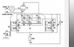
I also looked at the schematic but that is nothing special. Interesting is the control part in order to keep it safe. I would start building it with 1 tube only just to check how it performs and learn from that experience. Only then decide to continue building a bigger system or leave it at that.
I am not convinced that the Helium will just blow away from the plasma cloud as it will interact with the environment. So if the pressure is very low of the Helium flow it could be collected in a space above the plasma cloud to create a denser Helium cloud and less Helium is needed after all reducing the flow again and noise.
Hill claimed the noise was not an issue. It was around a liter a minute or something. He stresses how you have to move the heat out to maintain the correct temperature gradients. I suppose the gas might be piped out and recycled. I just think letting it flow out, grab it up along with an enclosure with an acoustically transparent window.
I will was building a HV amp anyway so i just need to check how i can construct a mini plasma cell to play with this....
Attachments
I will was building a HV amp anyway so i just need to check how i can construct a mini plasma cell to play with this....
Hill wrote of applying high current/low voltage to a copper tube to heat the gas. The opening of the tube becomes the cathode... I have some tungsten rods...
I've got a 60 milliamp neon in my junk. Got diodes coming, put an autotransformer on it after an isolation transformer...
Ever take the magnetic shunts out of a neon transformer?
The plus and minus 170 will be easy. Dang tubes go for about 20 to 30 US. There are others that would work, but I figure starting out it would be good to use the same tube.
The tubes can be replaced by cheaper versions. The PL519 is a better choice here (hence my name Lampie519) or any equivalent.
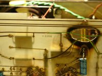
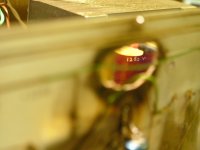
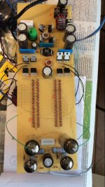
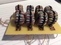
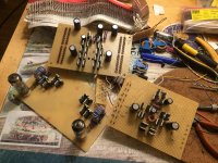
The powersupply can be created using an HV circuit like shown on the last picture (experimental HV amp). The first images are just to show the destructive nature of HV. So again, let’s be carefull!!
Using HF circuitry could improve the entire design as no monster transformers are needed and no dc voltages.
The tubes can be replaced by cheaper versions. The PL519 is a better choice here (hence my name Lampie519) or any equivalent.
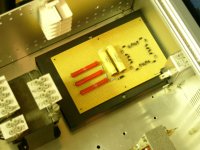
The powersupply can be created using an HV circuit like shown on the last picture (experimental HV amp).
Using HF circuitry could improve the entire design as no monster transformers are needed and no dc voltages.
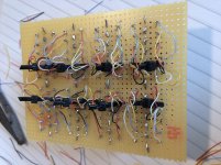
The 519 is a wicked cool tube. I like the idea. Would like to know more about that HV amp. Looks like there are over 100 diodes on it.
This amp uses a high frequency carrier that drives H-bridges to help transforming to the high voltage needed. The amount of diodes is needed as these can not handle the high voltage. Now there are other diodes but these are just not fast enough. I will try different diodes as well the next time. The diodes however will be in the signal path so they need to be as fast as possible.
Creating the high voltage this way is more efficient as we do not need any ballast resistors on the output tubes, The DC level can be adjusted on the lower end of the tube to increase the overall voltage to stabilize the plasma stream.
First i will have to finish this little amp i am working on.....
Attachments
Last edited:
I once heard a pair. That high end simply wasn't there-it was the most lifelike I had heard. Problem was the need for helium gas on a regular basis, the thrown out back lifting the big tanks for changeout, and the ozone. The midrange simply could not keep up with that tweeter. Bass was so-so. Tweeter was where it was at in spades.
There should not be any ozon as the flame should not create much UV light. The flame supposed to be more yellow (hence the use of helium).
In the past i used several plasma speakers but only the ones with flames generated ozon. The ones with a horn did not.
The sound is very nice but limited in frequence response. Building a "Plasmatronic clone" is tempting.
The helium is a pain but i think it is worth the effort to try building it anyway.
Matching it with other speakers will be the next chellenge. The nice thing of DIYérs is that we do not need to check how much it will cost as we do not need to make a profit.
I can match these with my ESL's if i want and filter these at 700Hz. They make good mids and bass (16hz).
Attachments
Last edited:
Dynamic drivers have improved quite a bit since the old plasma speaker days. Matching sound is likely easier than it was then.
Which brings up a whole other question: have dynamic drivers improved to the point where all the shenanigans of a plasma speaker aren't worth it?
I'm not trying to say they don't appeal to some listeners, but if they had a significant advantage over other technologies, you would think they would have gained more traction in the marketplace (at least for cost-no-object designs).
- Home
- Loudspeakers
- Planars & Exotics
- Hill Plasmatronics: Bit by the plasma bug