So just want to share my Eureka moment. Not much of a response on a thread I started about isobaric ESLs. I did not try it because of advisory info on another thread. But this is a bit different. I have a pair of Acoustat Monitor 3 with DD OTL monos. The panels are mounted on the back of the frame structure so there is a 1" set back/recess. I ordered 5/8" thick felt, same medium density as the strips on the backs already to tame resonance. So I cut and covered the entire front side of the panels with felt, filling the recess of each panel/frame recess. I then mounted a second set of panels on the front of the frame, sandwiching the felt. I did not remove the original felt strips on the backs of the second set. Guess what happened when I tapped on the front panels...Nothing! Dead, no resonance to speak of. How silly, right? But here's the trick.. I also hooked up a second set of DD OTLs!! So now there is full damping without loss of output. It's hard to describe just how much better they sound. There's no comparison. The rolled off top end character is gone, mid range is spectacular, that upper bass tubbiness is gone. Sound stage is far more enveloping/depth is just awesome. The sound is so close and intimate it's as if you're right up next to them. This is how they should have been designed in the first place. This tweak is anything but boring.
Just thought I'd mention it.")
Just thought I'd mention it.
Photographs would help our understanding of what you have done. 😊
Is additional felt the same shape as the original pads, or full coverage?
Are additional panels on all, or just outer 2 panels?
If the monitor 3 are similar to model 3, then the central panels are 8",rather than 9" and outer panels are angled back 10ish degrees from the plane of the central panels.
The description sounds easy, but the detail sounds complicated, if all 3 panels are not in the same plane.
Exciting though. 😉
Cheers
Grant
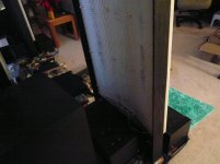
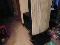
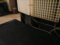
So you can see on the 4th pic the recess behind the panel. The frame is 1 inch thick. The originals are mounted on the backside while the second set on top. The felt is cut to fit each cavity between the panels. I removed the original felt strips off the backs, not needed.
Attachments
Last edited:
Okay I think I have it now.
The 1" depth is filled over the full area of the panel and the felt on the back, of the front panels compresses slightly into the new felt, over the area of the existing felt of the front panels. 10/8ths becomes 1" and in the perimeter out site the original felt pads, does not touch both panels.
Interesting, very interesting. I am tempted to try bolting one extra panel to the front of my 1+1's to see what this might do.
Do you use any room correction, or other DSP to play with EQ?
Cheers
Grant
No, there's a 1" thick frame with panels on either side of it. The cavity between them has 5/8" thick felt over the entire surface area. I left the existing original felt strips on the outer second set which you cannot see because it's on the back of those, also in the cavity against the full felt I put in there.
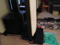
I have a pair of Linn 5150s to...augment...the bass
I also ordered 1/2" thick felt I can add to completely fill the cavity under a little pressure to carry it further, later on after this.
This makes it very apparent how much resonance affects the performance of these speakers. It's huge.
oops, after reading your response again, I think you do have it
I just have to add, I'm absolutely blown away by this. Floored! The more I listen, it's just WOW!
Last edited:
Woo hoo. ��
I will start out small, one panel centrally placed, covering 1/2 of the upper panel and 1/2 of the lower panel. Sounds like I need to rustle up another spare panel though, to do this properly. ��
Yes a little cheating on the bass never hurt anyone. ��
Best Wishes
Grant
I will start out small, one panel centrally placed, covering 1/2 of the upper panel and 1/2 of the lower panel. Sounds like I need to rustle up another spare panel though, to do this properly. ��
Yes a little cheating on the bass never hurt anyone. ��
Best Wishes
Grant
This is Very Cool!!
I am glad too see Finally somebody with enough panels to give this a try !!!
I wish I could hear it in person !!
There have been many discussions on such methods, I have done similar things with my Desktop sized ESL's and DIY'er WrineX has experimented with stacking small ESL's as well.
It sounds as though my predictions are correct using this method of stacking diaphragms.
You should get a more robust midrange that extends a bit lower and the low end should have a bit more control and lower THD I believe.
The only thing is I never finished my larger panels yet to explore this further myself.
The ML CLS-CLX (I forget which one) uses a stacked diaphragm in their bass panel section too, but they don't have any dampening in between them.
Dave Lucas's ESL subwoofer system uses two sets of three stacked diaphragms and uses an open cell foam in between each layer for dampening.
That is all I have on that system, plans can be found on the web now.
In my past tests when I was working with my panels, I knew that they needed some dampening but I was never satisfied when any type of material that got with in a few inches of the rear of the diaphragm.
it just seemed to ruin the high end detail no matter what I tried, so I never pursued it after that.
At that point in time I wasn't sure if it was worth the time to build extra panels to do this and not be able to utilise the extra surface area to increase the lowend gain.
For those panels raising the Bias voltage to +7Kv to +10Kv did the trick on those.
Now that I have experimented with Extreme voltage levels and how to use them on ESL's I think that this would be another nice study.
In order to compensate for the not having twice the surface area one can increase the D/S and have more excursion with higher voltages for the low end.
Stacked diaphragms will give you more control over diaphragm movement in general at high excursions of travel.
It was at this point of finishing my variable HV Bias supply back in 2012-13 that I discovered that I was able to have DC control over the movement of the diaphragm.
I have built my new frames in a way to easily observe this and they do handle the much higher voltages as to where I left off, with a variable D/S for bigger excursion testing as well.
Since then I took a break from it all and I am now Currently working on my DDamp design and it is coming along quite nicely !!
Once I get a new panel running again and get the concept amp above the 50v range I will start a thread on it and present it to the community too.
Cheers !!!
jer
Last edited:
Thanks for that response. Honestly, the more I listen to them this way, the more I'm blown away. Every attribute is on steroids. What you predict is spot on but with a lot more top end extension also. But the more striking thing is how much deeper the sound stage is in terms of perceived point source imaging. Sound decay is full and complete. I'm hearing information engineered into the track I had no idea was there. On all my music. It really is a fabulous discovery on my part. However I should point out I quickly lost interest in the interface driven topology when I acquired my set of DD OTL servo monos. The are in a different league already imo/e. So I have no impression or idea how this set up could work there. All I know is the King is definitely not dead.
I have been wanting a DD setup over the iron ever since before I built my very First ESL's in 2003.
I'd been working on designs in Circuit Maker Simulator ever since the mid 90's, after keeping David P Hermeyer's and Roger Sanders articles found in the 1980 Audio Amatuer Projects book by my side for 10 years prior and ever since !!
Sanders Sound Systems - Audio Related Articles
http://sanderssoundsystems.com/downloads/audio_amateur_one_1976_an_electrostratic_Amplifier.pdf
Built my First 200 volt powered DD amp in 2008 for kicks and giggles and it powered a piezo disk as a load, I used 3 or 4 60v IRF510's stacked up to handle the higher voltage.
I was quite impressed that it worked and worked well, with Good Sound Quality, Too !!!
But, At the time I didn't have any of my panels running anymore after they sat for 7 years, so refurbishing them came about in 2010, and since then I haven't yet had the time to re-visit the DDamp concept until now.
FWIW
jer
Last edited:
My stuff as scattered all through these threads !!
DIY electrostatic speakers for dummies
I never had anything altogether at once at the same time to start my own individual threads on stuff.
I have the original schematic of my First 200 volt amp in a thread here somewhere .........
Here,
Looking for HV fets for direct drive
All Discrete Class-A Headphone Amp
HVfet's here,
Looking for HV fets for direct drive
And my latest concept design is found here,
Any Direct Drive ESL Amp projects someone could share?
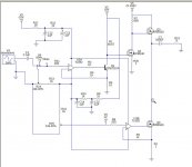
I have modified this circuit to use a BJT to drive the FET VAS stage as I had found in testing that the opamp itself does not create enough current to properly drive the FET at higher frequency's very well.
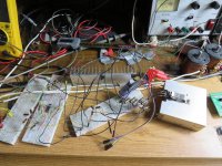
So I am using this configuration now ( as pictured below).
I have been using this schematic as built and tested to make my adjustments, as I had mentioned it is only at < 50V output supply.
Right now it is at 22V actually, but it works fantastic and I am blown away how great it sound despite the numbers !!!
THD is quite low as it is without any kind of feedback yet, and has a voltage gain of 47 as it sits.
NFB has not even been implemented yet and THD is about .05% to .12% and I had a worst case of .35% as measured and is ruler flat up to 200Khz to 300Khz range.
So, The Concept works !!!
But I have a ways to go before I can present a full working ESL driver to the DIY community.
I have been using this amp to power my Sony 5 /14" drivers that I have been using in developing the Desktop ESL System in past years.
Despite it being based off of using opamp's this amplifier design operates Fully in a Class A mode only, and, Bias Voltage operating point, Output Voltage and Output Stage Bias Current are all fully adjustable and operate separately from one another!!
Cheers and Enjoy !!!

jer
P.S. I am using STM FET's that I have as mentioned in the other thread links in this design so far drawing up PCB's as we speak in order to continue on to higher voltage testing.
DIY electrostatic speakers for dummies
I never had anything altogether at once at the same time to start my own individual threads on stuff.
I have the original schematic of my First 200 volt amp in a thread here somewhere .........
Here,
Looking for HV fets for direct drive
All Discrete Class-A Headphone Amp
HVfet's here,
Looking for HV fets for direct drive
And my latest concept design is found here,
Any Direct Drive ESL Amp projects someone could share?
I have modified this circuit to use a BJT to drive the FET VAS stage as I had found in testing that the opamp itself does not create enough current to properly drive the FET at higher frequency's very well.
So I am using this configuration now ( as pictured below).
I have been using this schematic as built and tested to make my adjustments, as I had mentioned it is only at < 50V output supply.
Right now it is at 22V actually, but it works fantastic and I am blown away how great it sound despite the numbers !!!
THD is quite low as it is without any kind of feedback yet, and has a voltage gain of 47 as it sits.
NFB has not even been implemented yet and THD is about .05% to .12% and I had a worst case of .35% as measured and is ruler flat up to 200Khz to 300Khz range.
So, The Concept works !!!
But I have a ways to go before I can present a full working ESL driver to the DIY community.
I have been using this amp to power my Sony 5 /14" drivers that I have been using in developing the Desktop ESL System in past years.
Despite it being based off of using opamp's this amplifier design operates Fully in a Class A mode only, and, Bias Voltage operating point, Output Voltage and Output Stage Bias Current are all fully adjustable and operate separately from one another!!
Cheers and Enjoy !!!
jer
P.S. I am using STM FET's that I have as mentioned in the other thread links in this design so far drawing up PCB's as we speak in order to continue on to higher voltage testing.
Attachments
Last edited:
Wow, you just compiled the entire past ESL activity here. Thank you. Great reference. Not that I could utilize the vast majority of it. I wish I had your knowledge. What do you think of the last query I suggested in substituting the felt for just MDF? Do you think there's sufficient space to cause turbulence and cancel the improvement? The idea is that output would be increased?
Yep, Your welcome, i used to recite that stuff of the top of my head quickly back in the day, I have several of those types of posts that I need to re-compile and put them up as a sticky.
"What do you think of the last query I suggested in substituting the felt for just MDF?"
Not sure what you mean here, Closing up the sides to seal the inside cavity?
Without the felt then you will have cavity resonances to contend with. but sealing up the sides may help with more control as the frequency gets lower.
Or are you thinking of using a slab of MDF to take up some of the inside volume for more control at lower frequency's.
I had just taped my frames together but this was not a perfect seal by any means.
There was a thread of a DIY'er that tried sealing up the back of his ML with some Fiberglass or Rock Wool or something and I have been waiting to hear more of his ventures of how it turned out.
He said it sounded good to him and that was where he left it in the thread, I am wondering if he is still running them like that.
I believe it was an effort to dampen the back wave to get more bass out of them without having to set them so far away from the back wall ( WAF ) .
At this point you should make some sweep tests with REW, the waterfall plot alone will tell you a lot when it comes to dampening, any good microphone will do, as long as you can see the changes of what you are hearing.
jer
"What do you think of the last query I suggested in substituting the felt for just MDF?"
Not sure what you mean here, Closing up the sides to seal the inside cavity?
Without the felt then you will have cavity resonances to contend with. but sealing up the sides may help with more control as the frequency gets lower.
Or are you thinking of using a slab of MDF to take up some of the inside volume for more control at lower frequency's.
I had just taped my frames together but this was not a perfect seal by any means.
There was a thread of a DIY'er that tried sealing up the back of his ML with some Fiberglass or Rock Wool or something and I have been waiting to hear more of his ventures of how it turned out.
He said it sounded good to him and that was where he left it in the thread, I am wondering if he is still running them like that.
I believe it was an effort to dampen the back wave to get more bass out of them without having to set them so far away from the back wall ( WAF
) . At this point you should make some sweep tests with REW, the waterfall plot alone will tell you a lot when it comes to dampening, any good microphone will do, as long as you can see the changes of what you are hearing.
jer
Last edited:
I was thinking of duplicating the exercise but using 1" thick MDF instead of felt and compare the results. The Monitor 3 frames are 1"thick and the panels are mounted on top of the backside so the incidental cavity in front is 1" deep. That's where the felt is in now with the second set of panels on top on the face side. So remove felt and sub in MDF. The only cavities that would be remaining is the volume of the louvers plus the distance to the outer edge of them from the diaphragm. That's the issue I'm wondering about. Is the air cavity just within the louvers enough to cause significant resonance. My own suspicion is yes. Right now output is seriously abundant but I'm wondering if resolution could be further enhanced without the felt dampening. I don't want to undo the positive results of the whole exercise.
Secondarily, since the felt I have in there now is only 5/8" thick and the cavity is a full 1", I was contemplating putting a thin hard barrier like sheet metal on top of the 5/8" felt and then adding another layer of 3/8" felt before installing the second set of panels. This way the two sets of panels are not atmospherically open to each other through the felt, the barrier sandwiched between the two layers of felt. So this way the two sets have zero interaction. Because at audio frequencies, the felt alone between them has no real ability to divide them but just provides dampening, no?
Secondarily, since the felt I have in there now is only 5/8" thick and the cavity is a full 1", I was contemplating putting a thin hard barrier like sheet metal on top of the 5/8" felt and then adding another layer of 3/8" felt before installing the second set of panels. This way the two sets of panels are not atmospherically open to each other through the felt, the barrier sandwiched between the two layers of felt. So this way the two sets have zero interaction. Because at audio frequencies, the felt alone between them has no real ability to divide them but just provides dampening, no?
Last edited:
Hi friends, I made isobaric bass panels consisting of 6 membranes and 8 stators made up of a package,they work very efficiently and dynamically. Diy ESL. - YouTube
Last edited:
- Status
- This old topic is closed. If you want to reopen this topic, contact a moderator using the "Report Post" button.
- Home
- Loudspeakers
- Planars & Exotics
- Isobaric ESL alternative