Hello,
I have been following the various threads about constructing segmented wire stators. All that I can recall use a series arrangement of resistors between the segments. However, one of the early threads also diagrammed a parallel resistor arrangement between stator segments. Can someone discuss the advantages of one technique vs the other or is it purely a cost of parts issue?
Thanks
Hi
Series form: The series form is actually an RC transmission line - look up the telegrapher's equations on wikipedia. Think of each ESL segment as a capacitor to see how this works in the equations. For a narrow, tall, ideally floor-to-ceiling ESL, this form has a couple of pieces of magic. Firstly, it provides near perfect equalisation - a flat frequency response over a very wide range of frequencies - for a full range ESL you need about 10 segments.
The other piece of magic is that it creates a very flat polar response - it gives the same SPL as you move off axis to either side of the centre of the speaker. In this respect it is better than most conventional loudspeakers. ESLs have a reputation for having a very small sweet spot -the head-in-a-vise effect. The RC transmission line design completely eliminates this problem. At high frequencies, only the central segments radiate a lot of acoustic power. At low frequencies, the whole panel radiates.
Parallel form: I have looked at this form on and off over the years and not found a way to make it work well. I think it can probably be made to work OK in a system where there is a seperate section for bass, midrange and treble, but it's not great. Also, it does not make efficient use of the panel area - ESLs need a lot of area to radiate useful levels of power at low frequencies, and having separate sections devoted only to midrange and treble does not make the most of the panel area.
There are now quite a few examples of the RC transmission line version described on this forum, so there are people with experience ready and willing to help with a design if you want. Jazzman's and bolserst's speakers are particularly well documented. Also, if you've following the threads, you may have noticed links to software tools. If you do not experience nausea with mathematics, I can send a paper that gives the design equations for the RC transmission line too. Just send a pm with your email address.
Thank you for your reply and explanation. I would appreciate the design equations and I will struggle with the math. I have followed Charlie's threads and have read Bolserts. Both have helpful information. I have tried to download the software to calculate the TL but my computer or my lack of computer skills prevents that. Ergo, my interest in your kind offer of the article.My email is jted@jastak.com. Thanks again.
Ted
Ted
ESLX?
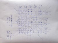
My basic idea is starting from vertically a segmented ESL. Now, why not double- or X-wise segment the two stators? By including another, a horizontal segmentation on one of the two stators, along with the vertical segmentation of the other stator? This would/might provide a more or less narrow HF-extended area in the middle, and more and more HF-attenuation not only horizontally, such as in all the «standard» segmented designs I know, but maybe also vertically.
Such a X-wise, or 2-dimensional segmentation would create zones of symmetrically applied forces, when both HT audio signals have the same frequency cutoff (I call it the IS-Zone), and also asymmetrically driven zones, when the back- and the front stator rods are fed with audio HT having different HF rolloffs (which I call the hetereo zones).
So there are questions over questions: Can such a setup like such an ESLX work at all? Maybe I neglect something important? And if it works, what would the expected drawbacks be? More phase distortion? More harmonic distortions emanating from the hetero zones? Is there any knowledge base about such ESLX approaches – and where to find these infos, if any?
ESLX.jpg
And what about cross-wise segmentation? I am quite shure that many ESL-designers und -builders already had the same idea about a crosswise segmented ESL. But I cannot find neither references, nor threads. So please point me to the correct references if there are any.... The series form is actually an RC transmission line - look up the telegrapher's equations on wikipedia. Think of each ESL segment as a capacitor to see how this works in the equations. For a narrow, tall, ideally floor-to-ceiling ESL, this form has a couple of pieces of magic. Firstly, it provides near perfect equalisation - a flat frequency response over a very wide range of frequencies - for a full range ESL you need about 10 segments.
The other piece of magic is that it creates a very flat polar response - it gives the same SPL as you move off axis to either side of the centre of the speaker. In this respect it is better than most conventional loudspeakers. ESLs have a reputation for having a very small sweet spot -the head-in-a-vise effect. The RC transmission line design completely eliminates this problem. At high frequencies, only the central segments radiate a lot of acoustic power. At low frequencies, the whole panel radiates.
My basic idea is starting from vertically a segmented ESL. Now, why not double- or X-wise segment the two stators? By including another, a horizontal segmentation on one of the two stators, along with the vertical segmentation of the other stator? This would/might provide a more or less narrow HF-extended area in the middle, and more and more HF-attenuation not only horizontally, such as in all the «standard» segmented designs I know, but maybe also vertically.
Such a X-wise, or 2-dimensional segmentation would create zones of symmetrically applied forces, when both HT audio signals have the same frequency cutoff (I call it the IS-Zone), and also asymmetrically driven zones, when the back- and the front stator rods are fed with audio HT having different HF rolloffs (which I call the hetereo zones).
So there are questions over questions: Can such a setup like such an ESLX work at all? Maybe I neglect something important? And if it works, what would the expected drawbacks be? More phase distortion? More harmonic distortions emanating from the hetero zones? Is there any knowledge base about such ESLX approaches – and where to find these infos, if any?
ESLX.jpg
Attachments
Is it possible vary loudness from center to edge making spherical shaded array?
Don Keele's CBT (Constant Beamwidth Transducer) Page
That would form perfect directivity speaker.
3-O LAB
Don Keele's CBT (Constant Beamwidth Transducer) Page
That would form perfect directivity speaker.
3-O LAB
The ESL you describe should mimic a point source. As best I can tell, when only resistors are used, you can get a good polar response, but not the flat frequency response. To get both, you must use the LC transmission line in the manner of the quad ESLs.
By using a series resistor - to give the constant current behaviour and flat frequency response required for the point source - you can flatten the frequency response a bit but you have to trade flatness of the response for low sensitivity.
By using a series resistor - to give the constant current behaviour and flat frequency response required for the point source - you can flatten the frequency response a bit but you have to trade flatness of the response for low sensitivity.
Hi
Perhaps my last post was too cryptic....
There are only three types of ESL that have a flat frequency response for all listening distances.
Point source: ESLs that mimic a point source - e.g., the Quad 63 family of ESLs, which simulate a spherical radiator. The acoustic radiation for these ESLs expands with a spherical wavefront. To get a flat frequency response, these ESLs must draw the same stator current at all frequencies - so they must have an impedance that looks like a pure resistance. This follows from Walkers equation, which relates the SPL to listening distance and stator current. You can do this by putting a single resistor in series with the panel, or by using the LC transmission line, as Quad do.
Planar source: ESLs that look like a planar source (like a wall) produce a flat wavefront giving the same SPL at all distances. These are not common, but ES headphones are in this class, as are near field monitors. For these, the stator current must increase in proportion to the frequency, so any ESL that looks like a pure capacitor will have a flat frequency response when operating in the mode. There is a different Walkers equation for planar sources, and another for line sources.
Line source: The line source operates between the other two. It produces an expanding cylindrical wavefront. This can be achieved using a narrow floor-to-ceiling ESL. It looks infinitely long acoustically because of the reflections off the floor and ceiling - imagine them as mirrors - you would see reflections of the ESL lined up with each other and disappearing off to infinity. The line source requires the stator current to increase in proportion to the square root of frequency. This can be achieved if the ESL is built to look like and RC transmission line. Coincidentally, the symmetric RC transmission line with connected at the centre segment has the nice polar response too.
Any ESL that does not behave like these cannot have a flat frequency response at all distances. For example, a single segment rectangular ESL, behaves like a plane source when you are very close, a line source at intermediate distances, and a point source at large distances, and the frequency response changes as the listener moves back. To get a flat response you will need to use some sort of electronic equalisation, and it will only work well for a small range of listening distances.
So, if you can find a segmentation scheme and RC network that has the same impedance at all frequencies, you can use it to mimic a point source and perhaps at the same time give a better polar response than a single segment ESL.
hope this helps
Thank you! These three models show that life is not meant to be easy ... and indeed are helpful in terms of motivator. I think by now, best thing to do, if I want to proceed into ESL's DIY, is to start a learning-by-doing experience with a small HW functional proto, e.g. some 20cm*40cm and then look how it behaves. And then try to understand the specific behavior.
I can see this working.
I have had in mind for a few years of trying to use a segmented front stator with a vertical orientation and a rear segmented stator tha has horizontal orientation.
The 45 degree offset as shown in post 4 IMHO would be labor intense and would serve no purpose to get the same effect.
I think if one were to give this a try I think that a square or circular shaped pattern for the diaphragm should be used.
If one were to choose a rectangular shaped diaphragm, I think that it would result in a distorted radiation pattern than what was intended and would be better off with just sticking to the front and back stators both in same direction as normally done in regular construction practices.
Cheers !!
jer")
I have had in mind for a few years of trying to use a segmented front stator with a vertical orientation and a rear segmented stator tha has horizontal orientation.
The 45 degree offset as shown in post 4 IMHO would be labor intense and would serve no purpose to get the same effect.
I think if one were to give this a try I think that a square or circular shaped pattern for the diaphragm should be used.
If one were to choose a rectangular shaped diaphragm, I think that it would result in a distorted radiation pattern than what was intended and would be better off with just sticking to the front and back stators both in same direction as normally done in regular construction practices.
Cheers !!
jer
- Status
- This old topic is closed. If you want to reopen this topic, contact a moderator using the "Report Post" button.
- Home
- Loudspeakers
- Planars & Exotics
- Segmented stator construction