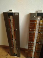
second version, pretty much the same construction, after some more investigation. I don't use a transformer. I built this JLH high power 2005 Geoff Moss Version/ TCAAS this amp does deliver enough current with very low imendance. Will update from the segmented ribbon with 2 tracks (ca. 2,5 Ohm) to an unsegmented ribbon whoch will be a little bit more than 1 Ohm -> next step. ..just send the measurements and pictures for comparison and motivation!
Attachments
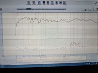
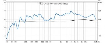
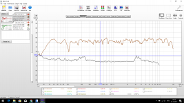
Hm looks similar in the freqence domaine. But dont understand my rising distortion ?. And your No baffel, do look like is better")
I doesn't make sense for me either. I think the measurement is wrong.
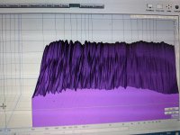
I measured, normal listening (loud) volume, mic. ca. 25cm away, 0°, to reduce room interference.
I had some issue: First I used my ECM8000 then bought a more expensive calibrated beyerdynamic. The Beyerdynamic measured more noise and distortion, so that was rare, so I kept on with the behringer..
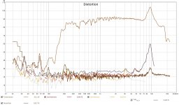
that rising THD is werid, definitely something wrong. what kind of mic you use since either the mic has allot of self noisee or the amp is not liking it much.
both the beyer dayton or the other one are based on the same .... rather crappy electred. at elast the amplification sucks.
i bought an ISEMcon still affordable... more expensive then the Umik witch also sucks for distortion. and i can measure numbers below 0.1%
both the beyer dayton or the other one are based on the same .... rather crappy electred. at elast the amplification sucks.
i bought an ISEMcon still affordable... more expensive then the Umik witch also sucks for distortion. and i can measure numbers below 0.1%
Attachments
Last edited:
to the mic so not the speaker those daytons have allot of self noise to. all the electrets measuring mics that dont even need phantom power. have allot of self noise i think () those 100euro/dollar mics
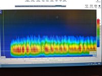
you can try measuring closer and see what the graph does, to eleiminate self noise. lower the input volume and crank up the speaker and put it real close. still it might be to much for the capsule. or the THD should drop. if so the mic selfnoise is a problem. else the mic distorts at high SPL or the speaker. you did calibrate the output ones ? so your not measuring a crappy soundcard or anything
also whats your average noise floor stated in the measurement. when it is rather silent in your room ? since mine is a 21dB in the last measurement almost 80 db down to the signal
those daytons have allot of self noise to. all the electrets measuring mics that dont even need phantom power. have allot of self noise i think () those 100euro/dollar micsyou can try measuring closer and see what the graph does, to eleiminate self noise. lower the input volume and crank up the speaker and put it real close. still it might be to much for the capsule. or the THD should drop. if so the mic selfnoise is a problem. else the mic distorts at high SPL or the speaker. you did calibrate the output ones ? so your not measuring a crappy soundcard or anything
also whats your average noise floor stated in the measurement. when it is rather silent in your room ? since mine is a 21dB in the last measurement almost 80 db down to the signal
Last edited:
that rising THD is werid, definitely something wrong. what kind of mic you use since either the mic has allot of self noisee or the amp is not liking it much.
both the beyer dayton or the other one are based on the same .... rather crappy electred. at elast the amplification sucks.
i bought an ISEMcon still affordable... more expensive then the Umik witch also sucks for distortion. and i can measure numbers below 0.1%
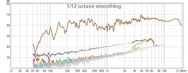
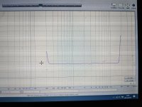
impressive! looks pretty clean both frequency plot and distortion numbers! congrats! ..which of your many projects is it?
its the push pull midrange with rubber magnets, i made a start to finish series about it few months ago. never got such low distortion to be honest. but the distortion is still visible. something i could not see with a umik. thats why i wonder if that might be the problem here
where did you got 4 My alu !!! i wonder
JLX Pure aluminum foil Luxury MKP film 10uF 100Vdc capacitor 1 piece ! - JIMS Audio
https://www.jbcapacitors.com/pdf/JL...Metallized-Polypropylene-Capacitors-Axial.pdf
maybe an option?
Not that powerfull after All.
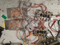
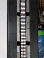
you should connect both pole pieces, lets say every 30cm with an iron bar the same thickness than the sides! ..this will make quite some difference in the magnetic flux in the gap. Your gap is pretty wide.. resulting in low magnetic force!
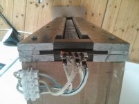
Return wire on bitumen. Make it Up as I go along
I would move the return wires away from the magnets, since this will cause energy losses through lorentz force which isnt necessary, also return wires should be silver coated thick cables, best several, as far away from the magnets as possible for lowest resistance. ..energy conversion should be reduced to the ribbon as much as possible! informatio = electrical energy, energy loss is loss in musical detail. So the transition needs to be as efficient as possible. Meaning reducing electrical losses and losses through excess weight of the ribbon. I would also try to get rid of your transformer, and direct drive (impendance will be 1-1,5 Ohm) with a suitable amplifier.
I dont think the it matters alot if the return wires are made of aluminium. The signal runs through 4 my aluminium in the ribbon . But the transformer. The next ribbon will be with out. 25 mm wide with 2 strips of alu 12 mm wide. Lets see if that doo the trick
And 2 meter long
. But the transformer. The next ribbon will be with out. 25 mm wide with 2 strips of alu 12 mm wide. Lets see if that doo the trickAnd 2 meter long
Last edited:
i used a NAD3020, Sanyo P55 and 12V Car 500 Watt Bricks, a Gainclone LM3886 to drive my ribbons which are pretty equal to your project. The biggest difference made trying a "JLH 1969" chinese class a kit.
Before i always was missing something in the sound. Thought it had something to do with digital sources DACs etc. (of course bad mastering can't be cured).
But after trying the JLH class a I had this moment.. never thought that it would make such an improvement!
another thing was getting rid of my minidsp and start with FIR filters (multichannel soundcard, EQAPO and rePhase).
Before I built the higher power version I used a classic JLH with 20V and 2A quiescent current (Documentation: google TCAAS). This design will loose about 40 Watt into the heatsinks. I was well sufficient for my ribbon which is divided into 2 stripes (2nd Version see photos) and has about 2,5 Ohms resistance. Anyways, now i wouldn't divide anymore. I would build it as a single stripe ribbon. What I would do is: I would lower the Voltage of the amp down to 10 or 12 V and increase the current to 4 A (also 40 Watt loss). This will make exactly the same effect and save a lot of work cutting the stripes.
Besides: if you have increased resistance through your return paths made by aluminium you'll loose 50% of your amplification power and need twice the voltage to compensate. This will mean you 'll have to double supply voltage of your amp and waste double of the energy (P=U*I) meaning probably it is not possible to cool the output transistors anymore. I would care to keep all resistance besides the ribbon to a minimum.
- Status
- This old topic is closed. If you want to reopen this topic, contact a moderator using the "Report Post" button.
- Home
- Loudspeakers
- Planars & Exotics
- Paper Sandwich ribbon