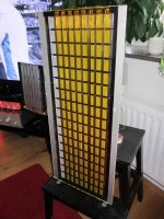
I had some magnets left from earlier projects, so I made this contraption for fun.
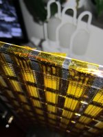
Its a bass driver with nine rows with 19 magnets in each row. The magnets size is 4x10x40mm, and a 12Um Mylar sheet stretched 4 mm over the magnets.
The perforated metal is a shelf from IKEA called "Bottna".
Today, it has four loops of 0.32 (28 gauge) copper wire. Each loop has four turns in the magnet gap. The loops are connected in series, giving a total of 5 Ohms and sensitivity around 85 dB/2,83 volt
The wires are taped to the Mylar using Kapton tape for easy replacement. (works surprisingly well, with very low distortion)
The big question: How to make the most Spl efficient wiring? Maybe using thinner wire in parallel?
Any suggestions?
Regards/ Jonas
Attachments
I like the simple and easily changeable construction. Great for experimenting!
IF you maintain 5 ohms then Thinner wire will lower sensitivity, yes even in parallel.
Assuming present configuration...
26 gauge copper will give you about 3 ohms and about 1.5- 2 db more
add another run of 26 ( 5 per ) and get about 3.8 ohms but only about 1 db more
Better If the magnets were closer together, about 1/4 inch apart would be good. Then field strength would be higher AND better aligned with wires field. If magnets closer together, and wire sized optimized, and assuming same size diaphragm, you should be able to get about 5 db, maybe a bit more
BTW if you stay with the magnets spread out like that you may not have good damping of both bass and lower mids. Its very "open". most planer designs have around a 10-15% open area through the magnet structure. Yours looks to be around 50% open area. This resistance to air movement is used to damp resonances. The kapton /wire/mylar sandwich might be giving needed damping but not likley. You may need to close up the construction a bit to quiet the ringing. This "ringing is heard as a boomy uncontrolled bass and a thick and resonant midrange.
You can easily experiment with this "damping" by simply attaching strips of any tape to the backside of magnet structure to close up the open areas. Try at 1/4, 1/2, 3/4 closed and listen. Be sure to rub tape down good to the perforated steel so that the tape doesnt move. I like to use the "painters tape". It sticks good enough BUT comes back off easily
Last edited:
If you look at Magnepan, the gap between magnets is small, about 2 mm. Magnepan uses weak magnets, plastic bounded ferrite. My old Magnepan tweeters, push-pull, have very little open area, about 11%. That causes some resonances and trapped high frequencies inside the driver. Did you not measure the B&G Neo 8 single sided?
Thank You, lowmax!
You are absolutely correct on the ringing phenomena, I can hear it in the mids.
I will try 6 mm between the magnets, and then I will also have space for a true ribbon tweeter on the same "Bottna".
Thanks again!
Yep a ribbon crossed around 400 hz will really make ya smile. Might be able to goto 1Khz BUT usually the vocals will suffer, although dynamics may seem better
Your magnets are a bit wide for really good mid and up operation. The width of those magnets limits them to good sound below 1 Khz so yes just tack on a ribbon and it can be quite good.
Also I would add a bit of baffle to the bass panel. I know, I dont like wide speakers eather BUT the improvement in bass is quite large
Last edited:
"Did you not measure the B&G Neo 8 single sided?" Yes, and it was much better singel sided.
My future goal is to try to mimic the sound of these speakers: YouTube.
I'm not saying that I'll be able to, but I'll give a try...Each speaker has over 50 kilograms of ferrite magnets....
My future goal is to try to mimic the sound of these speakers: YouTube.
I'm not saying that I'll be able to, but I'll give a try...Each speaker has over 50 kilograms of ferrite magnets....
It is push pull planar for the lower frequencies and ribbons for mid/tweeter. Price is very high. Just read they use neodymium magnets.
https://alsyvox.com/wp-content/uploads/2019/11/Alsyvox-value-proposition.pdf
https://alsyvox.com/wp-content/uploads/2019/11/Alsyvox-value-proposition.pdf
Last edited:
I had some magnets left from earlier projects, so I made this contraption for fun.
Its a bass driver with nine rows with 19 magnets in each row. The magnets size is 4x10x40mm, and a 12Um Mylar sheet stretched 4 mm over the magnets.
The perforated metal is a shelf from IKEA called "Bottna".
Today, it has four loops of 0.32 (28 gauge) copper wire. Each loop has four turns in the magnet gap. The loops are connected in series, giving a total of 5 Ohms and sensitivity around 85 dB/2,83 volt
The wires are taped to the Mylar using Kapton tape for easy replacement. (works surprisingly well, with very low distortion)
The big question: How to make the most Spl efficient wiring? Maybe using thinner wire in parallel?
Any suggestions?
Regards/ Jonas
if you want efficiency for bass use only, go thick alu wire(i still want to make one with almost pure wire vs open area on the mylar... as many other design ofcourse
 limited time). and use many turns. doubling the turns in the gap gives you +3dB, if you keep impedance the same that is. so twice the turns? you need thicker wire to achieve the same impedance.
It is push pull planar for the lower frequencies and ribbons for mid/tweeter. Price is very high. Just read they use neodymium magnets.
https://alsyvox.com/wp-content/uploads/2019/11/Alsyvox-value-proposition.pdf
i got my doubts about that design to be honest. the thickness of the panels is a big as the prommised excusion
an i bet it is not a real ribbon but a planar magnetic. and where do they hide all those thick neo's ? price is around 75000 for a medium pair i believe hahastill awesome looking, and the specs are really nice to (if correct). i must say. i would like to see a bit more from the inside since the prices are typical high end prices im always really sceptical
I think they had some drawings on their former (Italian) homepage. As far as I can remember, the magnets sits behind the teak decor. There have been a few reviews of them, very much praising the sound quality. Price is ridiculous…
I had a problem with there depth of 57mm i believe that include the teak strip and the magnets. Then they say 20mm excursion... either there magnets are super thin. Witch could be, or 20mm is xmax total swing so actually 10mm . I think the last but 20 sounds better of course. Why use the typical one way travel when stating xmax .....hehe
Anyhow love to have a peak inside to confirm what i believe push pull ribbed planar magnetic just like apogee.
Last edited:
Have we left these guy out ,or did I miss it...Analysis Audio....said to sound great
Was some info an pic.. here of the site, back in the days....all mylar bass with only Vertical foil runs …..single ended only.. any input...?
thanks
Audio...Analysis Audio
Was some info an pic.. here of the site, back in the days....all mylar bass with only Vertical foil runs …..single ended only.. any input...?
thanks
Audio...Analysis Audio
The Alsyvox must mean +/- 10 mm, which is a lot for a planar woofer. Maybe it is something like the Apogee woofers? The Apogees are are bit more long-stroke than Magnepan. Magnepan can do +/- 2 mm in the center of the diaphragm, nothing along the edges. Maybe +/- 1 mm average for the whole driver. A Magneplanar-style driver need to be large. Analysis Audio is also a bit different. The woofer has a surround of an elastic material that allows for more excursion.
... love to have a peak inside to confirm what i believe push pull ribbed planar magnetic just like apogee.
I believe the general arrangement is as you suspect. The patent application by the designer appears to mainly deal with details of construction, in particular stability of diaphragm tension while using thinner metal frame. But, I am basing that on the provided online English translation which may not be exact. Both attached...
FWIW, I heard them at RMAF last year and they were one of the few rooms I went back to multiple times to hear different types of music. Mids and highs were lovely with surprising amount of heft and definition in the bass range.
Attachments
Thanks for sharing this unexpected source for readily available powder coated perforated sheet steel....The perforated metal is a shelf from IKEA called "Bottna"
The Alsyvox must mean +/- 10 mm, which is a lot for a planar woofer. Maybe it is something like the Apogee woofers? The Apogees are are bit more long-stroke than Magnepan. Magnepan can do +/- 2 mm in the center of the diaphragm, nothing along the edges. Maybe +/- 1 mm average for the whole driver. A Magneplanar-style driver need to be large. Analysis Audio is also a bit different. The woofer has a surround of an elastic material that allows for more excursion.
Well, my experiments show that its almost impossible to make the stroke shorter, if using neodymium magnets! The force required to overcome the repelling effect is quite overwhelming in the case of a woofer with 300 magnets...
The stroke is one thing, the distance between magnets is another. I have made a double sided version of my woofer planar, and the stroke is never over +- 5mm using a 100watt amp. Also, there's very little difference in SPL, around +2 dB using front and back magnets.
Working on a new singelsided version now with two turns of 12uM Alu-strips as conductors, 6 mm wide and a total of 4 Ohms.
Working on a new singelsided version now with two turns of 12uM Alu-strips as conductors, 6 mm wide and a total of 4 Ohms.
The stroke is one thing, the distance between magnets is another. I have made a double sided version of my woofer planar, and the stroke is never over +- 5mm using a 100watt amp. Also, there's very little difference in SPL, around +2 dB using front and back magnets.
Working on a new singelsided version now with two turns of 12uM Alu-strips as conductors, 6 mm wide and a total of 4 Ohms.
push pull should gain 6dB in theory, usual 5db is more like realworld. but i think the reason for that is rather big xmax. with tweeters it raised 5db in my designs. about maggies there xmax is more like 1.2 mm spacers are 3.15mm 1-8th inch, and magnets are 2.2 +- mm since rubber is not so potent i think its not possible to make that much bigger, in push pull it should be possible at a cost of efficiency. like 1.5mm xmax and still gain a few db and have a tad higher xmax hence max spl. best benefit is reducing second order harmonics. downside is doing tweeters in this arrangement is hard. cavity resonances become a problem when using push pull as far as i know. depending on the thickness of the magnets
and the width of the spacing.. but since they are not so potent, spacijng is usually around 1 to 1.5mm between magnets
Last edited:
- Status
- This old topic is closed. If you want to reopen this topic, contact a moderator using the "Report Post" button.
- Home
- Loudspeakers
- Planars & Exotics
- Wiring a Planar