MDD Multi Delays Diffraction (version 2024.04)
The characteristics of the listening environment are very important for the quality of playback. With MDD technology, part of the energy emitted by the speakers is used to generate secondary sound fronts, the spherical fronts generated by diffraction are coherent, delayed and optimize interaction with the room. The emotions produced by listening to recorded music can also be obtained without treating the room acoustically and with economical broadband speakers. MDD Multi Delays Diffraction. The multiple emissions simulate three-dimensional sound sources, the delays optimize listening in environments that are not acoustically treated, the diffraction makes the speaker omnidirectional at all frequencies.
Acoustic loads are made with multiple waveguides. Each single waveguide adds secondary, delayed and coherent sound fronts to all sounds even if the recording was made with microphones positioned in non-ideal points. The primary and secondary emissions are reflected by the environment and reach the listener who perceives them as compatible with a three-dimensional source present in the room. Omnidirectional emission in a reflective environment increases the amount of waves reflected from the listening room. When the reflections of the recording room are reproduced due to the Haas effect, the brain perceives them as a continuation of the previous signals. The succession: primary wave, coherent and delayed secondary waves, reflections from the listening room, reflections from the recording room become a single sound for the brain that is easier to interpret and pleasant to listen to. It decreases the time needed for memory to decode sounds and increases the time available for imagination. Playback is similar to listening to instruments live in your room. It's not the most faithful conditions to the original recording but it can be a lot of fun. The listening area is large and you can better follow the music from every point of the room.
I have reorganized the material on MDD projects, there are three common components:
1 - mddOmni (3D effect, anti Haas effect, omnidirectional acoustic diffractor, sound recognition),
2 - mddTL (neutral cabinet, logarithmic sum),
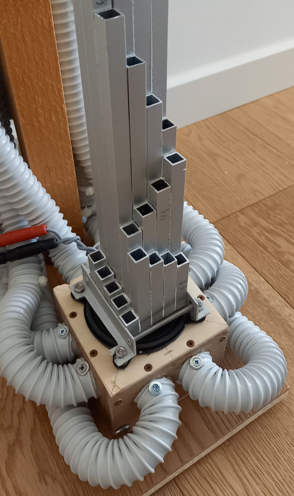
3 - subsonic resonance support (asymmetric base).
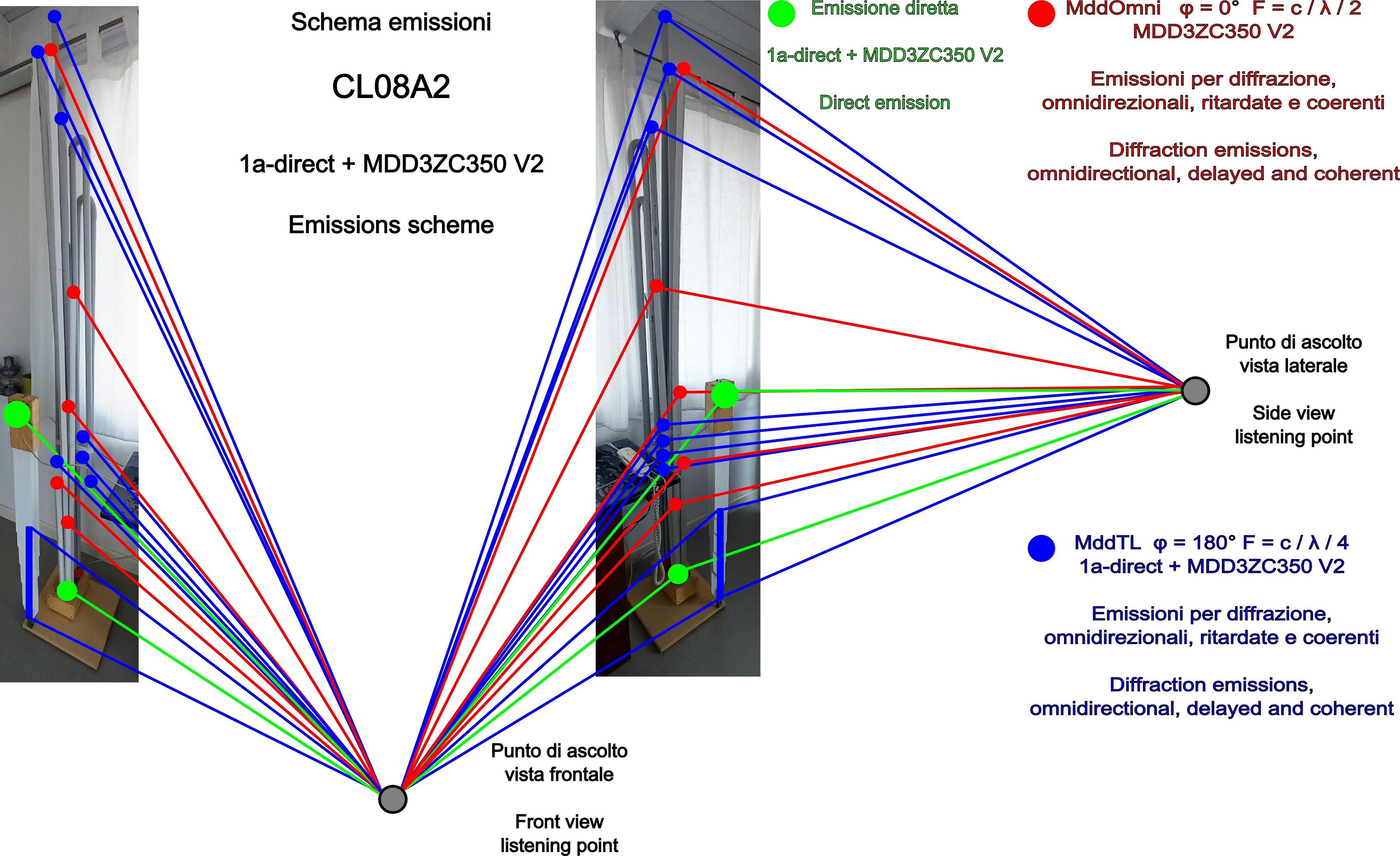
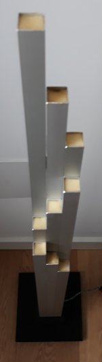
The mddOmni front acoustic load has sets of waveguides of increasing length positioned in front of the driver. A part of the acoustic energy emitted by the driver cone enters each guide. The same energy is re-emitted by acoustic diffraction, in different positions, with increasing delays, with spherical wave fronts and consistent with the direct emission of the driver. In the latest prototypes the guides are open on both sides with L/2 resonances. The driver's directional output becomes omnidirectional.
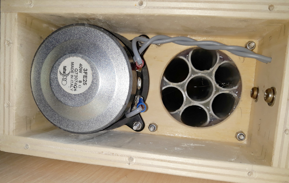
The mddTL rear acoustic load has multiple waveguides of increasing length attached to a compression chamber, it is a set of transmission lines with L/4 and L/2 resonant frequencies. At low frequencies the mddTL acoustic load is neutral with respect to the drivers and the listening environment.
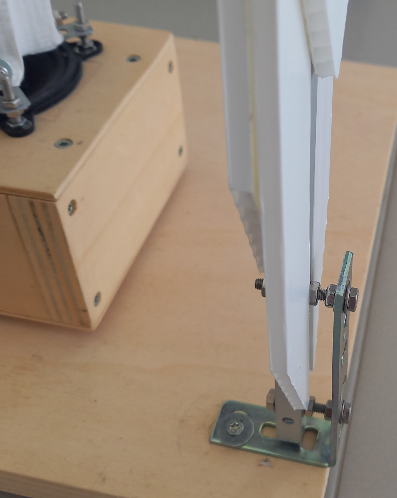
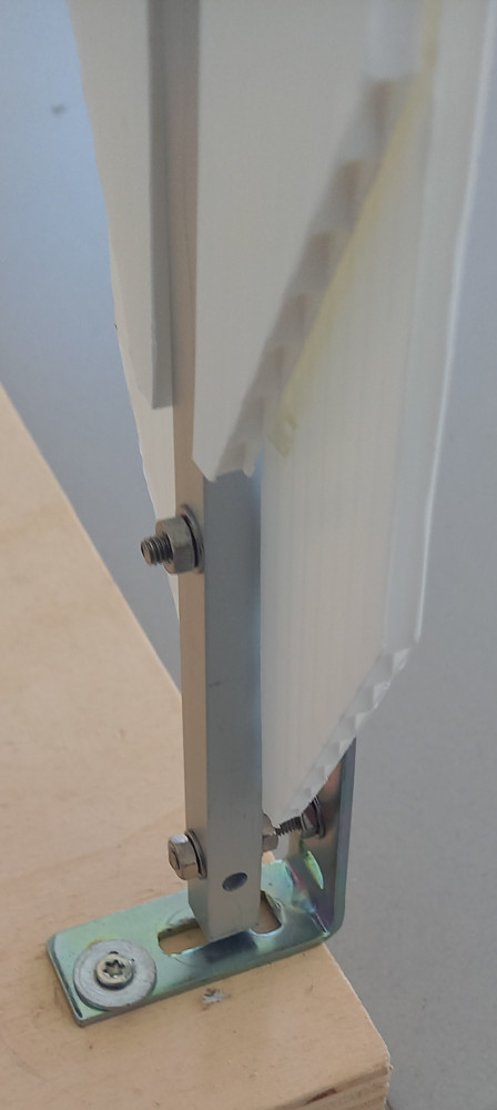
Subsonic resonance mount acoustically isolates the speaker from the floor in the audio band, improves reproduction detail. The asymmetric shape reduces the triggering of spurious vibrations.
Multiple emissions simulate three-dimensional sound sources. An instrument emits sounds from multiple points at the same time, the multiple emission points simulate the instrument in 3D. MDD speakers are not able to recreate the exact size of the original instrument but listening improves compared to the reproduction of a point source.
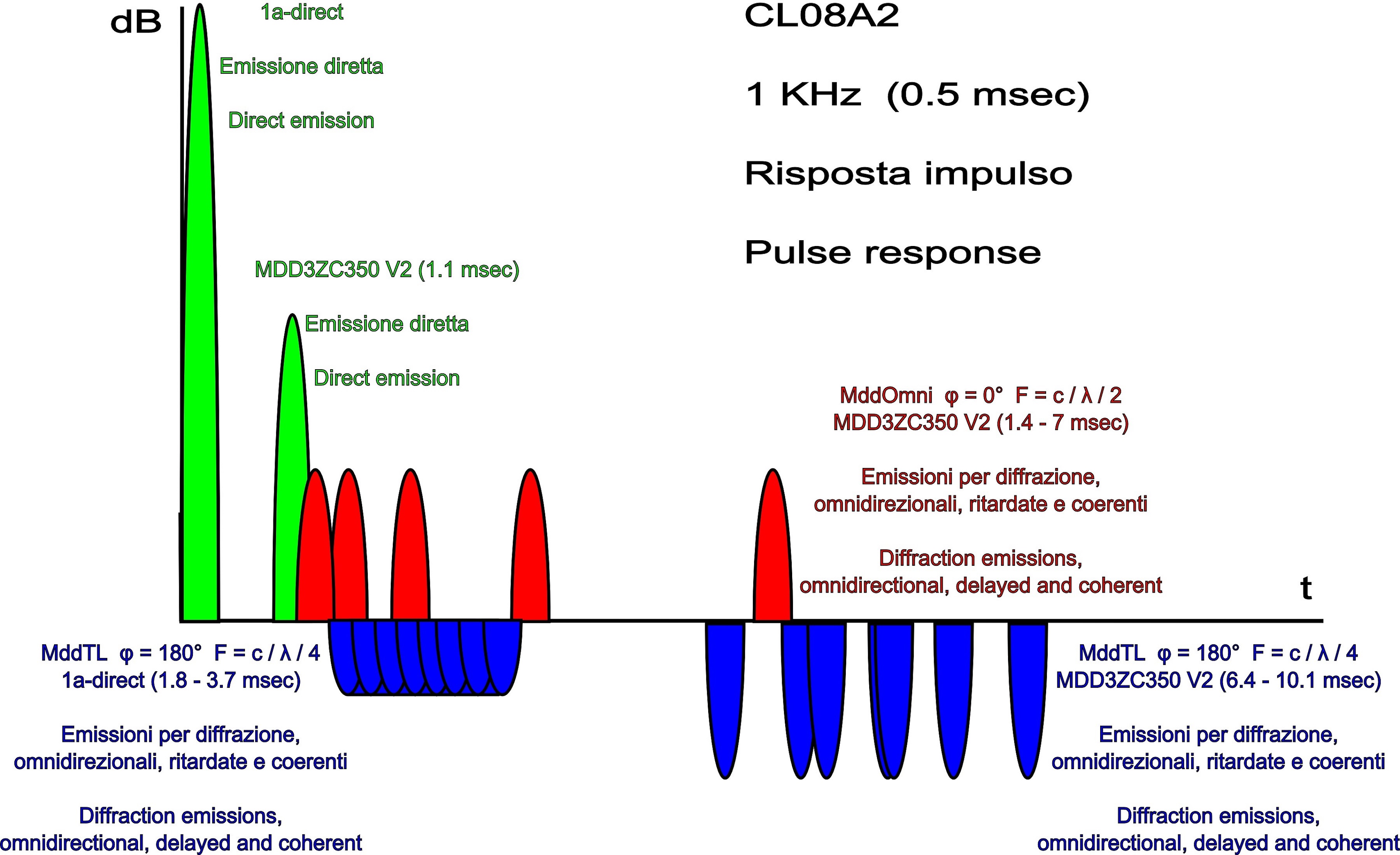
The Haas effect (precedence) occurs when two identical sounds arrive at the ear in succession. With delays greater than 5 milliseconds with simple sounds (clicks) the ear perceives distinct sounds. With more complex sounds the time increases to 40 milliseconds. The emission points of the mddOmni and mddTL acoustic loads are located at increasing distances from the driver and the secondary sound fronts have delays of between 1 and 10 milliseconds compared to the primary emission of the driver. The succession of sound fronts prevents the activation of the Haas effect, a single event cannot be perceived as two distinct sounds.
In standard TL speakers a waveguide is used as an acoustic screen to reproduce low frequencies. In general, the longer the guide, the greater the extension of the low frequencies, but the problem of interaction with the response of the loudspeaker and nearby walls must be resolved. The design of the mddTL rear acoustic load is much simpler. Multiple waveguides are used with the lengths calculated with the same formula that determines the frequencies of musical notes, the resonances of the waveguides are distributed homogeneously over an octave. With logarithmic series lengths the speaker is neutral with respect to the frequency response of the driver and the listening environment.
80dB + 80dB = 83dB,
80dB+60dB~80dB,
60dB + 60dB = 63dB.
other links
The characteristics of the listening environment are very important for the quality of playback. With MDD technology, part of the energy emitted by the speakers is used to generate secondary sound fronts, the spherical fronts generated by diffraction are coherent, delayed and optimize interaction with the room. The emotions produced by listening to recorded music can also be obtained without treating the room acoustically and with economical broadband speakers. MDD Multi Delays Diffraction. The multiple emissions simulate three-dimensional sound sources, the delays optimize listening in environments that are not acoustically treated, the diffraction makes the speaker omnidirectional at all frequencies.
Acoustic loads are made with multiple waveguides. Each single waveguide adds secondary, delayed and coherent sound fronts to all sounds even if the recording was made with microphones positioned in non-ideal points. The primary and secondary emissions are reflected by the environment and reach the listener who perceives them as compatible with a three-dimensional source present in the room. Omnidirectional emission in a reflective environment increases the amount of waves reflected from the listening room. When the reflections of the recording room are reproduced due to the Haas effect, the brain perceives them as a continuation of the previous signals. The succession: primary wave, coherent and delayed secondary waves, reflections from the listening room, reflections from the recording room become a single sound for the brain that is easier to interpret and pleasant to listen to. It decreases the time needed for memory to decode sounds and increases the time available for imagination. Playback is similar to listening to instruments live in your room. It's not the most faithful conditions to the original recording but it can be a lot of fun. The listening area is large and you can better follow the music from every point of the room.
I have reorganized the material on MDD projects, there are three common components:
1 - mddOmni (3D effect, anti Haas effect, omnidirectional acoustic diffractor, sound recognition),
2 - mddTL (neutral cabinet, logarithmic sum),
3 - subsonic resonance support (asymmetric base).
mddOmni
The mddOmni front acoustic load has sets of waveguides of increasing length positioned in front of the driver. A part of the acoustic energy emitted by the driver cone enters each guide. The same energy is re-emitted by acoustic diffraction, in different positions, with increasing delays, with spherical wave fronts and consistent with the direct emission of the driver. In the latest prototypes the guides are open on both sides with L/2 resonances. The driver's directional output becomes omnidirectional.
mddTL
The mddTL rear acoustic load has multiple waveguides of increasing length attached to a compression chamber, it is a set of transmission lines with L/4 and L/2 resonant frequencies. At low frequencies the mddTL acoustic load is neutral with respect to the drivers and the listening environment.
subsonic resonance support with asymmetric base
Subsonic resonance mount acoustically isolates the speaker from the floor in the audio band, improves reproduction detail. The asymmetric shape reduces the triggering of spurious vibrations.
3D effect
Multiple emissions simulate three-dimensional sound sources. An instrument emits sounds from multiple points at the same time, the multiple emission points simulate the instrument in 3D. MDD speakers are not able to recreate the exact size of the original instrument but listening improves compared to the reproduction of a point source.
anti Haas effect
The Haas effect (precedence) occurs when two identical sounds arrive at the ear in succession. With delays greater than 5 milliseconds with simple sounds (clicks) the ear perceives distinct sounds. With more complex sounds the time increases to 40 milliseconds. The emission points of the mddOmni and mddTL acoustic loads are located at increasing distances from the driver and the secondary sound fronts have delays of between 1 and 10 milliseconds compared to the primary emission of the driver. The succession of sound fronts prevents the activation of the Haas effect, a single event cannot be perceived as two distinct sounds.
omnidirectional acoustic diffractor
Acoustic diffraction makes the speaker omnidirectional at all frequencies. According to Huygens' principle, every point on a sound wave front is a secondary source of spherical waves. The end of the waveguides of the mddOmni and mddTL acoustic loads are omnidirectional emission points of a linear acoustic diffractor across the entire audio spectrum.neutral cabinet
In standard TL speakers a waveguide is used as an acoustic screen to reproduce low frequencies. In general, the longer the guide, the greater the extension of the low frequencies, but the problem of interaction with the response of the loudspeaker and nearby walls must be resolved. The design of the mddTL rear acoustic load is much simpler. Multiple waveguides are used with the lengths calculated with the same formula that determines the frequencies of musical notes, the resonances of the waveguides are distributed homogeneously over an octave. With logarithmic series lengths the speaker is neutral with respect to the frequency response of the driver and the listening environment.
logarithmic sum
80dB + 80dB = 83dB,
80dB+60dB~80dB,
60dB + 60dB = 63dB.
other links
psychoacoustics
asymmetric base
CL08A2
Last edited:
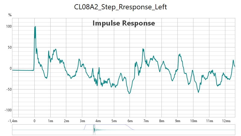
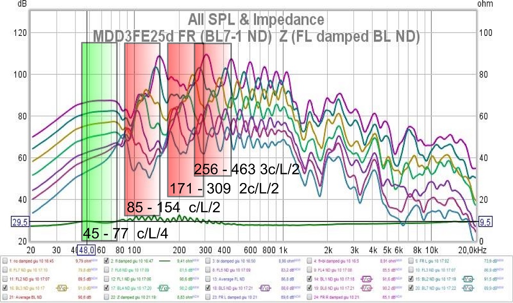
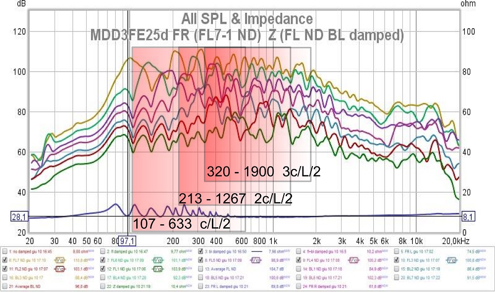
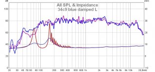
To eliminate the series of impedance peaks I prefer to increase the number of waveguides, the frequency differences between the peaks are reduced and overlap. The result is visible in the project impedance graph 54m42 with 42 wave guides. The use of damping material undoubtedly eliminates the individual peaks but risks attenuating the high frequencies that pass through the waveguides before being diffused in the listening environment. While listening, I am unable to detect the presence of peaks in the impedance and the effect of the geometry of the listening environment is much greater in the course of the FR.Some of that looks interesting. The ripples in the impedance denote each individual pipe, some damping might help. These can also be seen in the FR.
This concept looks a lot like it is related to Hedgeman’s work on speakers, but with the TL termi outside the box.
dave
I did a quick search on Hedgeman's work but found only some photos and nothing on the internal structure, if you can indicate some links to deepen it I would facilitate the search. I can't say anything for now.
Attachments
I wonder if a spiral arrangement (with the longest pipe in the middle) would work in the same way as the standard zig-zag for the square aluminium tube version.
It depends on the level of acoustic reflection of the wall behind the speakers. If you have a wall, or other, acoustically reflective, the energy emitted in that direction at high frequencies arrives at the listener with any arrangement of the tubes.
I tried the zigzag arrangement to direct (by reflection) part of the acoustic energy at high frequencies towards the listener. The intention is to remedy the attenuation of the high frequencies that I have encountered in environments treated acoustically with absorbent materials.
A driver with a flat axis response is normally directive at high frequencies. This implies that the sound energy emitted in the listening environment at high frequencies (concentrated in a frontal lobe) is lower than that of the medium and low frequencies. If the same driver is configured as perfectly omnidirectional, a drop in high frequencies is inevitable, in certain environments it may be perceptible. The advice is to do tests.
Just like with stereo movies, I think the stereo concept of home music is over-blown. Two speakers sound greatly better than one no matter where you sit or face backwards even. Spatial localization is only one small piece of music quality production.
And the sound of stuff is as much "social construction" as the ancient paintings of horses in caves. You can't truly capture any but the littlest instruments and bring them into your room with the stereo concept.
So, I think Claudio is asking the right questions.
And the sound of stuff is as much "social construction" as the ancient paintings of horses in caves. You can't truly capture any but the littlest instruments and bring them into your room with the stereo concept.
So, I think Claudio is asking the right questions.
To eliminate the series of impedance peaks I prefer to increase the number of waveguides, the frequency differences between the peaks are reduced and overlap. The result is visible in the project impedance graph 54m42 with 42 wave guides. The use of damping material undoubtedly eliminates the individual peaks but risks attenuating the high frequencies that pass through the waveguides before being diffused in the listening environment. While listening, I am unable to detect the presence of peaks in the impedance and the effect
Certainly extensive damping/absorption would attenuate the high frequencies. You may be able to employ something less aggressive to tame the resonances though. Thin felt may be an option.
In general, you may find audiophiles reluctant to embrace techniques that use highly resonant structures. The assumption is that energy storage and release obscures detail. This kind of coloration isn't always obvious at first. Direct comparison to highly resolving speakers or headphones can help highlight them. A high resolution distortion sweep is worth trying also.
Please don't take any of the above as criticism of your approach. I don't have direct experience with your design, so can't say how it sounds. Even if it has theoretical issues, the benefits could outweigh them. There are always trade-offs.
...reluctant to embrace techniques that use highly resonant structures
The DML is looking like it might be a counterexample. And fullranges above a certain point operate in a “resonant” manner. How good a FR is is often how well those resonant structures are controlled.
dave
How do you mean?fullranges above a certain point operate in a “resonant” manner. How good a FR is is often how well those resonant structures are controlled.
Below a certain point A FR acts as a piston, above a certain range the goal is for a growing part of the cone disengaging from reproducing the signal. The higher frequency behaviour is “resonant behaviour”, how well a FR does up top is a measure of how well the designer did on getting the resonant part of the behaviour to behave in a smooth manner.
dave
dave
Service communication. To participate in this forum I use Google Translator both in reading and writing. If I had to give unclear answers or off-topic, the cause could also be translation. In the strictly technical posts it is easier for me, others like this require me more time.Just like with stereo movies, I think the stereo concept of home music is over-blown. Two speakers sound greatly better than one no matter where you sit or face backwards even. Spatial localization is only one small piece of music quality production.
And the sound of stuff is as much "social construction" as the ancient paintings of horses in caves. You can't truly capture any but the littlest instruments and bring them into your room with the stereo concept.
So, I think Claudio is asking the right questions.
The post reminded me that I did not specify that my projects are alternative to the ideal point source concept. For me the point source is not ideal.
The omnidirectional speakers made with directional loudspeakers (almost all) suffer a reduction of the total energy at high frequencies due to the redistribution of the energy of the frontal lobe to 360 degrees. For this reason I do not recommend the use of damping material for those who want to replicate the MDD project. The material would also reduce the useful section of the wave guide.Certainly extensive damping/absorption would attenuate the high frequencies. You may be able to employ something less aggressive to tame the resonances though. Thin felt may be an option.
In general, you may find audiophiles reluctant to embrace techniques that use highly resonant structures. The assumption is that energy storage and release obscures detail. This kind of coloration isn't always obvious at first. Direct comparison to highly resolving speakers or headphones can help highlight them. A high resolution distortion sweep is worth trying also.
Please don't take any of the above as criticism of your approach. I don't have direct experience with your design, so can't say how it sounds. Even if it has theoretical issues, the benefits could outweigh them. There are always trade-offs.
Resonances are cyclical energy transfer between parts of a system. If the acoustic energy is stored by a panel of the cabinet that returns it distorted and out of phase there is a deterioration of the reproduction. With MDD technology the resonances of the waveguide allow the transfer of sound energy from the cone of the loudspeaker to the room where you listen.
One of the advantages of MDD technology is the lack of internal surfaces capable of generating reflections and consequently minimizes the possibility of cabinet resonances.
Another minimized resonance in MDD projects is that with the floor. The 2-3 Hz subsonic resonance bracket prevents the moving parts of the loudspeaker from generating audio frequency interactions with the floor.
In the envelope of a note (Attack, Decay, Sustain, Release) the sustain phase can be assimilated in a first approximation to a steady state. In this phase it is the presence of resonant waveguides that allows the transfer of energy from the cone to the listening room.
At the moment I don't want to convince audiophiles, these discussions allow me to better describe the functioning of MDD technology and to improve the projects by successive steps. The plays will also come.
So I had a chance to have a short listen with my workshop amp. In short, very interesting!
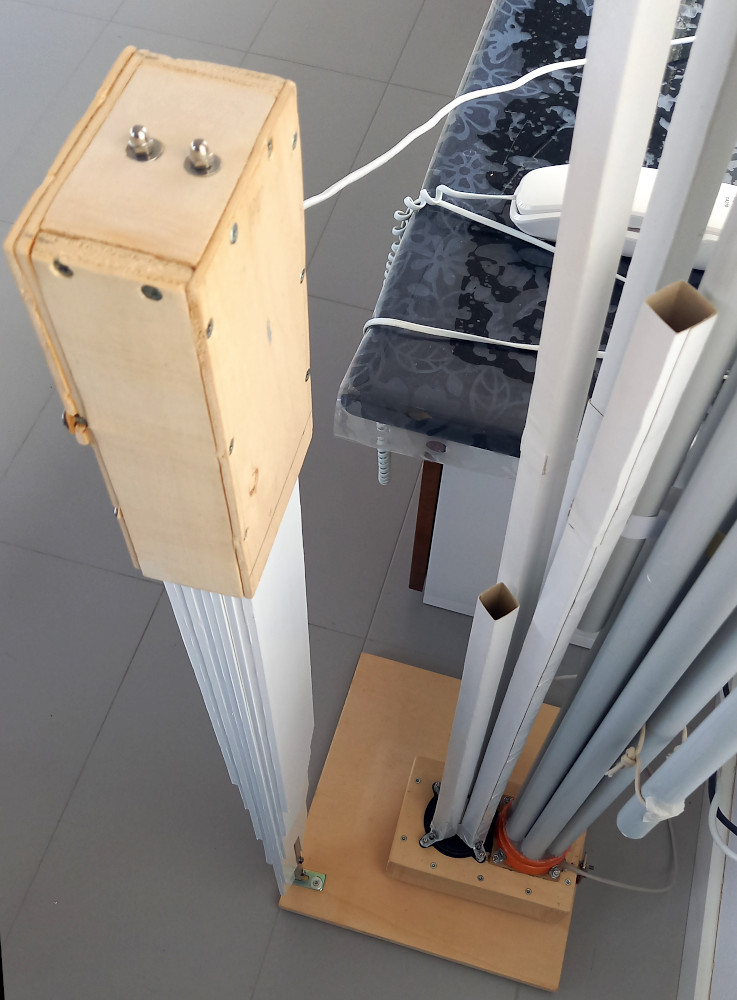
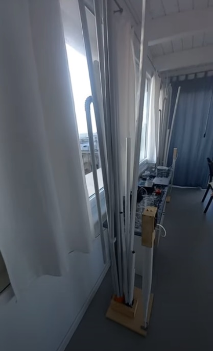
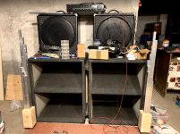
I only could listen for like 30 minutes jumping through the tracks I use normally for evaluating speakers. The only direct comparison I had was a pair of Fane 12-250TC in suboptimal boxes (not a fair comparison, but the Fanes sounded inferior - not that they are bad, not at all). Also, I could only listen at low level not to disturb the sleeping family. The picture shows the temporary arrangement, the speakers using the bass horns behind them as holders")
In the first few seconds, the sound felt strange, very different to anything I've heard so far. The soundstage felt like it was either a half circle extending around the two towers or maybe large as a triangle base extending from the speakers to the front wall.
On Andrew Allen Trio's Star War songs, the drums in the set were very convincingly spaced, like a real (smaller) drum set, I could even hear the stick hitting different places of the cymbals (I think). The instruments were placed where I am used to, but again a bit more "spacious" for the lack of words I have to describe this. I could move left and right a bit, the images were still placed in the same place until I went to a boundary, where objects in the room interfered (the room is far from empty and non symetrical). It is hard to believe that the sound comes from the metal pipes, it looked more like the speakers behind them played the music. There was absolutely no hint of the thing I hate the most - instruments localized at the speakers. A very 2D presentation (in the floor-parallel plane). I am really happy with the project, it is amazing what two small speakers can do with a very simple to build enclosure. The things I do not like are only connected to the limitation of the 3FE22 drivers. I miss some high end - but that might be also due to the very damped conditions around the speakers. Also, as expected, there is no real bass extension. And the last thing is, they are not 100 dB/W sensitive
I had a feeling that I could hear a metallic hint in the sound due to the aluminium, but I bet that was just a psychological matter seeing the pipes.
So these call definitely for some subwoofer arrangement and maybe some indirect firing tweeter. I immediately wondered how a Lowther would sound with this style of loading. Or maybe a Fostex or Sonido. Also, when there will be no bass played (crossed over at around 100 Hz) by them, I think I could skip the springy holder and the weight of the tubes should not be a problem.
I tried one side zig-zag, the other one spiral - I could not hear any difference in this limited test, for the final product, I will decide on the one that looks better to me.
This little project deserves to get into the finished state with permanently glued polished tubes and nicely looking bases. The total cost was around 80 Eur for both drivers and material. Also timewise, I did not spend many hours working on it.
I will ditch neither my large horn system nor my Hedlund horns, but these definitely deserve their place. They are enjoyable to listen to, they will get used most probably during late night low level listening sessions. So now I will work on finishing them, on my side there is no need for more listening tests. When finished, there will be a build thread with pictures.
Claudio, thank you very much for sharing your idea here!!! I think everyone should try to build a pair - maybe it is not the ultimate HiFi, but it is very enjoyable.
The next step in this project (somewhere in the future) will be using a high sensitivity FR loudspeaker, maybe with transparent acrylic tubing for looks. Heck, maybe I will try to use the Sonido SFR200A I already have. And maybe loading the back with a horn or pipe could take care of the bass needs? Ideas to test for sure I also wonder how that will compare to the Unitized waveguide project, which is controlling directivity in another way.
I only could listen for like 30 minutes jumping through the tracks I use normally for evaluating speakers. The only direct comparison I had was a pair of Fane 12-250TC in suboptimal boxes (not a fair comparison, but the Fanes sounded inferior - not that they are bad, not at all). Also, I could only listen at low level not to disturb the sleeping family. The picture shows the temporary arrangement, the speakers using the bass horns behind them as holders
In the first few seconds, the sound felt strange, very different to anything I've heard so far. The soundstage felt like it was either a half circle extending around the two towers or maybe large as a triangle base extending from the speakers to the front wall.
On Andrew Allen Trio's Star War songs, the drums in the set were very convincingly spaced, like a real (smaller) drum set, I could even hear the stick hitting different places of the cymbals (I think). The instruments were placed where I am used to, but again a bit more "spacious" for the lack of words I have to describe this. I could move left and right a bit, the images were still placed in the same place until I went to a boundary, where objects in the room interfered (the room is far from empty and non symetrical). It is hard to believe that the sound comes from the metal pipes, it looked more like the speakers behind them played the music. There was absolutely no hint of the thing I hate the most - instruments localized at the speakers. A very 2D presentation (in the floor-parallel plane). I am really happy with the project, it is amazing what two small speakers can do with a very simple to build enclosure. The things I do not like are only connected to the limitation of the 3FE22 drivers. I miss some high end - but that might be also due to the very damped conditions around the speakers. Also, as expected, there is no real bass extension. And the last thing is, they are not 100 dB/W sensitive
I had a feeling that I could hear a metallic hint in the sound due to the aluminium, but I bet that was just a psychological matter seeing the pipes.
So these call definitely for some subwoofer arrangement and maybe some indirect firing tweeter. I immediately wondered how a Lowther would sound with this style of loading. Or maybe a Fostex or Sonido. Also, when there will be no bass played (crossed over at around 100 Hz) by them, I think I could skip the springy holder and the weight of the tubes should not be a problem.
I tried one side zig-zag, the other one spiral - I could not hear any difference in this limited test, for the final product, I will decide on the one that looks better to me.
This little project deserves to get into the finished state with permanently glued polished tubes and nicely looking bases. The total cost was around 80 Eur for both drivers and material. Also timewise, I did not spend many hours working on it.
I will ditch neither my large horn system nor my Hedlund horns, but these definitely deserve their place. They are enjoyable to listen to, they will get used most probably during late night low level listening sessions. So now I will work on finishing them, on my side there is no need for more listening tests. When finished, there will be a build thread with pictures.
Claudio, thank you very much for sharing your idea here!!! I think everyone should try to build a pair - maybe it is not the ultimate HiFi, but it is very enjoyable.
The next step in this project (somewhere in the future) will be using a high sensitivity FR loudspeaker, maybe with transparent acrylic tubing for looks. Heck, maybe I will try to use the Sonido SFR200A I already have. And maybe loading the back with a horn or pipe could take care of the bass needs? Ideas to test for sure
I also wonder how that will compare to the Unitized waveguide project, which is controlling directivity in another way.Attachments
The material would also reduce the useful section of the wave guide.
I was thinking of a thin layer of felt at the pipe inputs or outputs, not lining them. Pipes aren't my specialty though, so I don't know if that will get you much.
So I had a chance to have a short listen with my workshop amp. In short, very interesting! ...
In the first few seconds, the sound felt strange, very different to anything I've heard so far. ...
I think everyone should try to build a pair - maybe it is not the ultimate HiFi, but it is very enjoyable. ...
Hi pelanj
this morning I found on the forum two replicas of MDD projects (a real and a virtual one), after all the work done is a great satisfaction.
Before talking about your post I want to point out the realization (virtual) of elleman https://www.diyaudio.com/forums/full-range/341739-34c9-mdd-range-speakers-4.html#post5915845 He reinterpreted the 439h project with radial wave guides.
I fully subscribe to your post. The 34c9 project was not designed for Hi-End, I think it is very difficult to do better with a 3 "driver like the 3FE22 (or 3FE25).
You have already identified some problems related to the first modalities of your test, I add some indications also referring to the photo you sent.
Low volume listening penalizes systems that already have limitations at the ends of the audio band (curve loudness), but what you hear is with inaudible distortion. Increasing the volume shortens the break-in and you can also hear the notes of the bass (not in the foreground). 80 dB is enough.
In the photo the environment is not very acoustically reflective.
Replacing simple rows with low-capacity cables can improve listening to the extremes of the band.
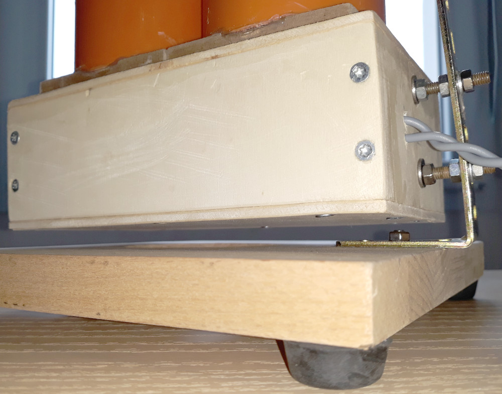
From the photo it seems that the magnets are resting directly on the floor, the adoption of the subsonic resonance bracket gives a further contribution to the quality of reproduction.
If you want to make a Hi-End project, I think you need to change the speaker and take longer lengths. MDD technology allows you to choose between various options according to your needs.
Thanks to pelanj for the first test.
Last edited:
Hi Claudio,
we are in perfect agreement. The speakers are on a spring leg, some 5 mm above floor and can freely move. The leg of the spring is held by the weight of the bass horn, the stands are not finished yet. This was just a quick listen in non ideal conditions. I consider this size to be perfect from 100 Hz up and will use a subwoofer below that. It is actually amazing, what a pair of small speakers can do. There is a potential to the design. I definitely want to try this system with a large full range speaker. The next step will be either a Delco 6.5" or maybe even the Sonido. When I have some less busy time, I will try the paper tubes, that is a very quick way to try. The 3D printed tubes are a great inspiration, I think it could work for the larger speakers, too.
we are in perfect agreement. The speakers are on a spring leg, some 5 mm above floor and can freely move. The leg of the spring is held by the weight of the bass horn, the stands are not finished yet. This was just a quick listen in non ideal conditions. I consider this size to be perfect from 100 Hz up and will use a subwoofer below that. It is actually amazing, what a pair of small speakers can do. There is a potential to the design. I definitely want to try this system with a large full range speaker. The next step will be either a Delco 6.5" or maybe even the Sonido. When I have some less busy time, I will try the paper tubes, that is a very quick way to try. The 3D printed tubes are a great inspiration, I think it could work for the larger speakers, too.
HelloCertainly extensive damping/absorption would attenuate the high frequencies. You may be able to employ something less aggressive to tame the resonances though. Thin felt may be an option.
In general, you may find audiophiles reluctant to embrace techniques that use highly resonant structures. The assumption is that energy storage and release obscures detail. This kind of coloration isn't always obvious at first. Direct comparison to highly resolving speakers or headphones can help highlight them. A high resolution distortion sweep is worth trying also.
Please don't take any of the above as criticism of your approach. I don't have direct experience with your design, so can't say how it sounds. Even if it has theoretical issues, the benefits could outweigh them. There are always trade-offs.
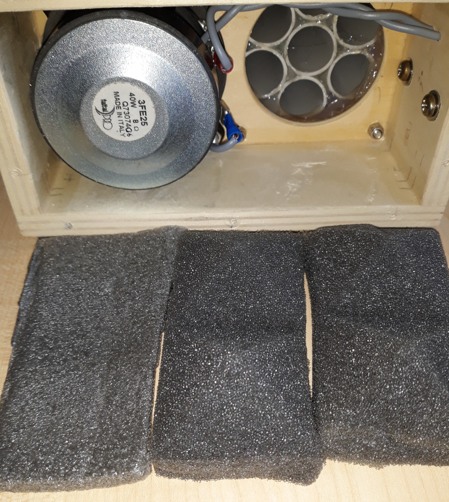
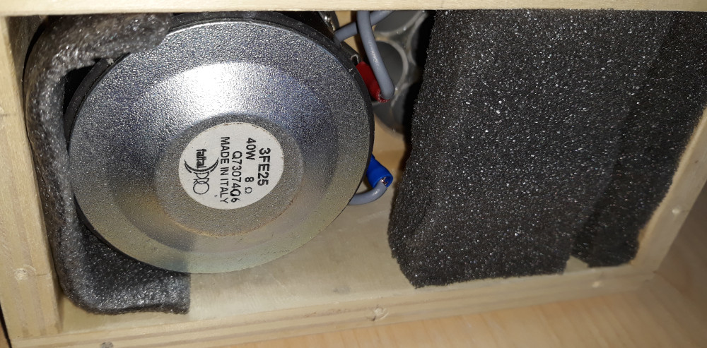
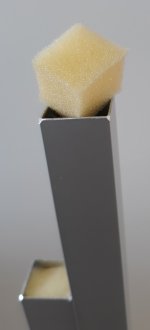
other people have also asked me what happens when inserting damping material.
I thought of a very simple and quick test, foam cubes. I feared a strong of the highs instead the foam rubber is almost transparent acoustically.
Results. A very slight attenuation on the highs. A greater general equilibrium probably due to the evident reduction of the peaks in the impedance module.
The system is simpler and cheaper than the increase in the number of wave guides and I will adopt it also in the next projects.
link: 34c9
Attachments
Last edited:
- Home
- Loudspeakers
- Planars & Exotics
- MDD Multi Delays Diffraction (Multi TL, omnidirectional, single drive, ...)