Thanks for the appreciation.
The corrugated pipe that whistles easily is the lightest, it is used in the wiring inside the walls.
The spiral sheath for outdoor that I used in the MDD3J240 project has another problem, probably caused by the aging of the plastic material. It absorbs 155 Hz as seen from the frequency response. I measured the same frequency value for sheaths of different lengths. However, its use was the simplest way to study the relationship between frequency response and wavelengths. Now I am trying other materials.
Attachments
Last edited:
MDD3Z200
The MDD3Z200 prototype is an evolution of the MDD3F25d project.
The base is the same as the MDD3M150 prototype.
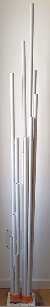
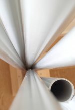
The front acoustic load is the same as the prototype MDD3F25d with 7 rigid PVC circular waveguides. The acoustic load is mounted raised by 10 mm to increase the efficiency by a few dB.
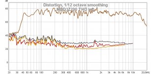
The rear acoustic load is the same as the prototype MDD3F25d with 7 rigid PVC circular waveguides. I have eliminated almost all the gluing leaving only the one at the base. Guides are now slightly divergent and can vibrate without interacting with neighboring waveguides. The distortion measure has improved.
Claudio Gandolfi - MDD (Multi Delays Diffraction Loudspeaker)
https://www.claudiogandolfi.it/mdd3a89.html#z
The MDD3Z200 prototype is an evolution of the MDD3F25d project.
The base is the same as the MDD3M150 prototype.
The front acoustic load is the same as the prototype MDD3F25d with 7 rigid PVC circular waveguides. The acoustic load is mounted raised by 10 mm to increase the efficiency by a few dB.
The rear acoustic load is the same as the prototype MDD3F25d with 7 rigid PVC circular waveguides. I have eliminated almost all the gluing leaving only the one at the base. Guides are now slightly divergent and can vibrate without interacting with neighboring waveguides. The distortion measure has improved.
Claudio Gandolfi - MDD (Multi Delays Diffraction Loudspeaker)
https://www.claudiogandolfi.it/mdd3a89.html#z
Attachments
MDD3R150 with MDD Tube
The MDD3R150 prototype is an evolution of the MDD3M150 project.
The base is the same as the MDD3M150 prototype.
The rear acoustic load is the same as the prototype MDD3M150 in 5 mm alveolar polypropylene and a maximum height of 1500 mm.
The front acoustic load is made of rigid PVC with a single tube with a diameter of 80 mm and a length of 1000 mm, MDD Tube. The front acoustic load is mounted raised by a few mm with L-shaped brackets in order not to decrease efficiency. The time saved in bonding in this prototype was dedicated to making the series of holes. The four series of 5 mm holes generate by diffraction coherent secondary waves with delays from 0 to 3 milliseconds.
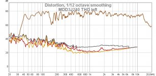
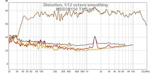
The distortion measurement shows small peaks between 1.5 and 3 KHz that I cannot perceive when listening. Perhaps they are due to the L-brackets made by hand with shears and pliers.
The sound is very good. The MDD Tube front load is a valid alternative to the front loads with multiple guides.
https://www.claudiogandolfi.it/
https://www.claudiogandolfi.it/mdd3a89.html#r
The MDD3R150 prototype is an evolution of the MDD3M150 project.
The base is the same as the MDD3M150 prototype.
The rear acoustic load is the same as the prototype MDD3M150 in 5 mm alveolar polypropylene and a maximum height of 1500 mm.
The front acoustic load is made of rigid PVC with a single tube with a diameter of 80 mm and a length of 1000 mm, MDD Tube. The front acoustic load is mounted raised by a few mm with L-shaped brackets in order not to decrease efficiency. The time saved in bonding in this prototype was dedicated to making the series of holes. The four series of 5 mm holes generate by diffraction coherent secondary waves with delays from 0 to 3 milliseconds.
The distortion measurement shows small peaks between 1.5 and 3 KHz that I cannot perceive when listening. Perhaps they are due to the L-brackets made by hand with shears and pliers.
The sound is very good. The MDD Tube front load is a valid alternative to the front loads with multiple guides.
https://www.claudiogandolfi.it/
https://www.claudiogandolfi.it/mdd3a89.html#r
Attachments
MDD3Q150 with MDD FL 7
The MDD3Q150 prototype is also an evolution of the MDD3M150 project.
The base is the same as the MDD3M150 prototype.
The rear acoustic load is the same as the prototype MDD3M150 in 5 mm alveolar polypropylene and a maximum height of 1500 mm.
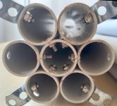
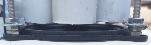
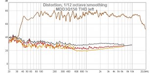
The front acoustic load (MDD FL 7) uses 7 rigid PVC waveguides with a diameter of 25 mm and a maximum length of 1600 mm, it is the front load of the modified MDD3Z200 project. The front acoustic load is mounted raised by a few mm with L-shaped brackets in order not to decrease efficiency. I have eliminated all the glues. The guides are now secured with six screws at the base only, are slightly divergent and can vibrate without interacting with neighboring waveguides. The distortion measure has improved.
https://www.claudiogandolfi.it/
https://www.claudiogandolfi.it/mdd3a89.html#q
The MDD3Q150 prototype is also an evolution of the MDD3M150 project.
The base is the same as the MDD3M150 prototype.
The rear acoustic load is the same as the prototype MDD3M150 in 5 mm alveolar polypropylene and a maximum height of 1500 mm.
The front acoustic load (MDD FL 7) uses 7 rigid PVC waveguides with a diameter of 25 mm and a maximum length of 1600 mm, it is the front load of the modified MDD3Z200 project. The front acoustic load is mounted raised by a few mm with L-shaped brackets in order not to decrease efficiency. I have eliminated all the glues. The guides are now secured with six screws at the base only, are slightly divergent and can vibrate without interacting with neighboring waveguides. The distortion measure has improved.
https://www.claudiogandolfi.it/
https://www.claudiogandolfi.it/mdd3a89.html#q
Attachments
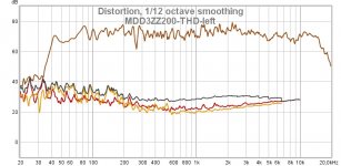
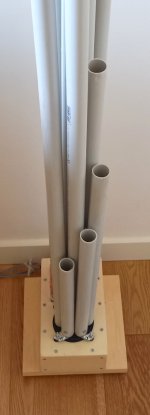
MDD3ZZ200
I have two new projects ready that use frontal acoustic loading (MDDFL) with diverging waveguides.
In the MDD3ZZ200 project, the vibrations that travel up the 7 waveguides can mechanically interfere only at the base. The improvement in listening quality is perceptible compared to the front load glued along the entire length as in the MDD3Z200 project.
Claudio Gandolfi - MDD (Multi Delays Diffraction Loudspeaker)
MDD3A89
Attachments
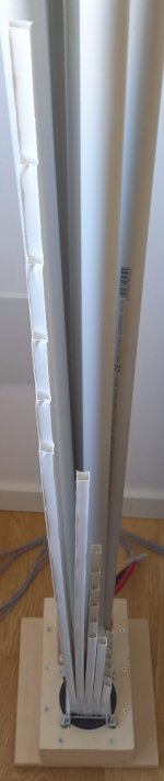
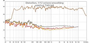
MDD3ZD200
In the MDD3ZD200 project, the vibrations that travel up the 30 waveguides can mechanically interfere only at the base or with the two waveguides of similar length. This is the system I have been using for about a month with great satisfaction.
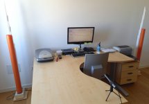
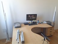
I listen to about 80 dB in a 4 x 4 x 3 room, the band goes from 40 Hz to 15 Khz, the distortion is reduced, you can recognize many details of the tracks being played. The symmetrical coherent and delayed signals in the two channels generate a good stereo scene even in a reflective and untreated environment. The omnidirectional emission releases the listening position from the vertex of the isosceles triangle with the speakers at the base. If I listen sitting at the desk the instruments are located beyond the wall behind the monitor. If I listen from the sofa, on the wall opposite the speakers, the stereo image remains behind the monitor but is wider. In neither case am I at the vertex of an isosceles triangle.
Claudio Gandolfi - MDD (Multi Delays Diffraction Loudspeaker)
MDD3A89
In the MDD3ZD200 project, the vibrations that travel up the 30 waveguides can mechanically interfere only at the base or with the two waveguides of similar length. This is the system I have been using for about a month with great satisfaction.
I listen to about 80 dB in a 4 x 4 x 3 room, the band goes from 40 Hz to 15 Khz, the distortion is reduced, you can recognize many details of the tracks being played. The symmetrical coherent and delayed signals in the two channels generate a good stereo scene even in a reflective and untreated environment. The omnidirectional emission releases the listening position from the vertex of the isosceles triangle with the speakers at the base. If I listen sitting at the desk the instruments are located beyond the wall behind the monitor. If I listen from the sofa, on the wall opposite the speakers, the stereo image remains behind the monitor but is wider. In neither case am I at the vertex of an isosceles triangle.
Claudio Gandolfi - MDD (Multi Delays Diffraction Loudspeaker)
MDD3A89
Attachments
MDDFL in alveolar polypropylene for ribbon tweeter
I propose again a suggestion already given.
The front acoustic load (MDDFL) in alveolar polypropylene can be easily adapted for use with ribbon or planar tweeters in multi-way systems. To create a prototype, it takes about one square meter of 10 mm alveolar polypropylene shaped in panels fixed with a double flange suitable to be mounted about 10 mm above the horizontally positioned tweeter.
I don't have multi-way systems available, but I can give suggestions to those who want to experiment with MDD technology with planar tweeters, making them omnidirectional.
Claudio Gandolfi - MDD (Multi Delays Diffraction Loudspeaker)
MDD3A89
Attachments
MDD3ZD350
For some time I have wanted to create an MDD prototype with Lmax = 2 Lmin = 4 meters and a resonant frequency of about 20 Hz. Does the improvement in listening justify the effort to manage the construction complications? Yes.
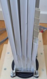
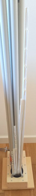
I had already disassembled the 7 waveguides of the 21M7 project with Lmax = 2Lmin = 1400 mm and I used them as extensions of the guides of the MDD3ZD200 project with Lmax = 2Lmin = 2000 mm. The new series has Lmax = 2Lmin = 3400 mm, the resonant frequency is about 25 Hz.
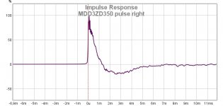
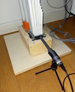
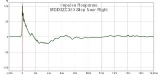
As expected the low frequency response has improved but this is not the only positive effect. The longer acoustic load also reduces the displacement of the cone at lower frequencies, the driver's response to transients is appreciably improved. The response to the step was measured with the microphone a couple of cm from the cone and with a reduced volume.
Claudio Gandolfi - MDD (Multi Delays Diffraction Loudspeaker)
MDD3ZD350
For some time I have wanted to create an MDD prototype with Lmax = 2 Lmin = 4 meters and a resonant frequency of about 20 Hz. Does the improvement in listening justify the effort to manage the construction complications? Yes.
I had already disassembled the 7 waveguides of the 21M7 project with Lmax = 2Lmin = 1400 mm and I used them as extensions of the guides of the MDD3ZD200 project with Lmax = 2Lmin = 2000 mm. The new series has Lmax = 2Lmin = 3400 mm, the resonant frequency is about 25 Hz.
As expected the low frequency response has improved but this is not the only positive effect. The longer acoustic load also reduces the displacement of the cone at lower frequencies, the driver's response to transients is appreciably improved. The response to the step was measured with the microphone a couple of cm from the cone and with a reduced volume.
Claudio Gandolfi - MDD (Multi Delays Diffraction Loudspeaker)
MDD3ZD350
Attachments
MDD3ZZ350 ("listening pleasure")
In this video (in Italian) of the Velut Luna channel I heard an operational definition of "listening pleasure" that I share. I summarize. A system is pleasant to listen to if you are sorry not to be able to use it, if during listening an unexpected interruption is perceived as annoying, if you listen for a long time it does not create fatigue or the desire to change tracks. The same video emphasizes the importance of the voice used as a tool for optimizing the reproduction system. Our hearing is an extremely complex spectrum analyzer that has its maximum sensitivity on the medium frequencies, evolution has selected the best possible tool to recognize and understand us. With this prototype, my pleasure and attention in listening to the voices in the songs played increases.
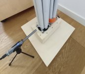
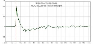
Even this latest prototype MDD3ZZ350 is a recombination of parts already used previously. The MDDBL rear acoustic load uses the series Lmax = 2Lmin = 3400 mm of the MDD3ZD350 prototype, the resonance frequency is about 25 Hz. The front acoustic load is of the MDD FL 7 type with seven 25 mm rigid PVC waveguides. .
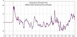
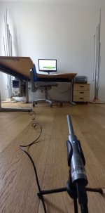
The response to the step was measured first with the microphone a couple of cm from the cone, with the volume reduced and then with the microphone on the floor at normal volume (80 dB) in front of the sofa.

In the second measure you can clearly see the numerous replicas of the step are generated: by the secondary emissions at the output of the waveguides and by the reflections on the walls. The MDD technology behaves as if acoustic panels were applied to the smooth walls of my room that generate multiple reflections with different delays.
In this video (in Italian) of the Velut Luna channel I heard an operational definition of "listening pleasure" that I share. I summarize. A system is pleasant to listen to if you are sorry not to be able to use it, if during listening an unexpected interruption is perceived as annoying, if you listen for a long time it does not create fatigue or the desire to change tracks. The same video emphasizes the importance of the voice used as a tool for optimizing the reproduction system. Our hearing is an extremely complex spectrum analyzer that has its maximum sensitivity on the medium frequencies, evolution has selected the best possible tool to recognize and understand us. With this prototype, my pleasure and attention in listening to the voices in the songs played increases.
Even this latest prototype MDD3ZZ350 is a recombination of parts already used previously. The MDDBL rear acoustic load uses the series Lmax = 2Lmin = 3400 mm of the MDD3ZD350 prototype, the resonance frequency is about 25 Hz. The front acoustic load is of the MDD FL 7 type with seven 25 mm rigid PVC waveguides. .
The response to the step was measured first with the microphone a couple of cm from the cone, with the volume reduced and then with the microphone on the floor at normal volume (80 dB) in front of the sofa.
In the second measure you can clearly see the numerous replicas of the step are generated: by the secondary emissions at the output of the waveguides and by the reflections on the walls. The MDD technology behaves as if acoustic panels were applied to the smooth walls of my room that generate multiple reflections with different delays.
Attachments
Last edited:
@claudiogan do you think MDD could be applied to a BG neo8s driver (planar magnetic mid/tweeter)?
I’ve been toying with the idea to make som ambience speakers with time delay to go with my main speaker (2-way 12” woofer and planar tweeter).
I’ve been toying with the idea to make som ambience speakers with time delay to go with my main speaker (2-way 12” woofer and planar tweeter).
Hi Pepe.@claudiogan do you think MDD could be applied to a BG neo8s driver (planar magnetic mid/tweeter)?
I’ve been toying with the idea to make som ambience speakers with time delay to go with my main speaker (2-way 12” woofer and planar tweeter).
Yes.
Acoustic diffraction works linearly with any sound wave front. It is simple to divide the front on several waveguides that re-emit the energy at their end. The outgoing wave fronts are omnidirectional, delayed and consistent with the front at the entrance.
In MDD technology:
1 - the omnidirectional emission over the entire acoustic spectrum improves listening in the whole environment, you are no longer bound to the position of the vertex of the isosceles triangle with the base between the two speakers;
2 - multiple delays between 0 and 6-10 milliseconds reduce the possibility that the Haas effect creates listening fatigue, delays of a few milliseconds without acoustic energy can make two signals that have a single origin perceive as distinct;
3 - (not in the case of mid-tweeters) the waveguides of the MDDBL rear acoustic loading are a simpler and cheaper system of horns and TLs to reach 4 linear meters, with a resonance frequency of 20 Hz.
I have never tested with two-way systems, with planar mid-tweeters or with sound pressures over 90 dB. I have already suggested an idea for building a first prototype of the MDD mid-tweeter. If someone wants to send a drawing of his, I can help with the calculation of the lengths of the waveguides.
Attachments
MDD3ZC350
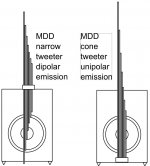
In recent months I have spent a lot of time listening to music with the MDD3ZZ350 prototype, I have made small improvements in relation to the elimination of spurious vibrations generated near the screws and waveguide supports in the MDDFL front acoustic load. With this new MDD3ZC350 prototype I tried to eliminate the spurious vibrations generated by the waveguide material. By replacing rigid PVC with cardboard, you pass from a material with a high elasticity to an inelastic material.
In rigid PCV the speed of sound is 1700 m / sec. The sound fronts transmitted in the air inside the wave guide (341 m / sec) interact minimally at the exit of each guide with the vibrations transmitted in the rigid PVC but generated at different instants.
Cardboard is an inelastic material that does not carry acoustic energy. At the output of the waveguides, the sound fronts that have traveled inside the guide do not interact with vibrations emitted at different times and transmitted by the cardboard.
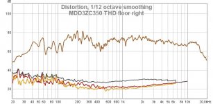
At the level of measures I have not noticed any differences but at the level of listening we perceive the improvement. Standard measurements are not able to describe the behavior of a speaker in the presence of complex signals such as a musical recording interacting with the listening environment.
The waveguide material is not the only change for the front acoustic load:
https://www.claudiogandolfi.it/
https://www.claudiogandolfi.it/mdd3a89.html#zc350
In recent months I have spent a lot of time listening to music with the MDD3ZZ350 prototype, I have made small improvements in relation to the elimination of spurious vibrations generated near the screws and waveguide supports in the MDDFL front acoustic load. With this new MDD3ZC350 prototype I tried to eliminate the spurious vibrations generated by the waveguide material. By replacing rigid PVC with cardboard, you pass from a material with a high elasticity to an inelastic material.
In rigid PCV the speed of sound is 1700 m / sec. The sound fronts transmitted in the air inside the wave guide (341 m / sec) interact minimally at the exit of each guide with the vibrations transmitted in the rigid PVC but generated at different instants.
Cardboard is an inelastic material that does not carry acoustic energy. At the output of the waveguides, the sound fronts that have traveled inside the guide do not interact with vibrations emitted at different times and transmitted by the cardboard.
At the level of measures I have not noticed any differences but at the level of listening we perceive the improvement. Standard measurements are not able to describe the behavior of a speaker in the presence of complex signals such as a musical recording interacting with the listening environment.
The waveguide material is not the only change for the front acoustic load:
- it passes from 7 waveguides to 5, Lmax = 8Lmin = 2000 mm (379, 574, 871, 1320, 2000 mm)
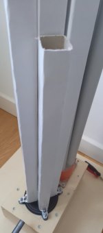
- the section of the guides is square 20 x 20 mm,
- the guides are arranged in a cross and create four further open 90-degree waveguides on the outside.
https://www.claudiogandolfi.it/
https://www.claudiogandolfi.it/mdd3a89.html#zc350
Attachments

MDD3ZC350 V2
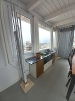
About 6 months ago I tried to listen to the MDD3ZC350 prototype on the veranda, it stayed there. The floor is in ceramic tiles (in the other room it was in floating parquet), the ceiling is in wood with exposed beams (it was in plasterboard) the walls are: one in masonry, one with windows and two glass windows (there were three in masonry and one in plasterboard). The room is wider and lower 5 x 6 x 2.5 m (was 4 x 4 x 3 m). The combination of the geometry of the room, the materials and the furnishings has significantly improved the quality of the reproduction. I had confirmation of the importance of listening room acoustics. The MDD prototypes perform well in reflective environments and here I have two and a half walls of glass. I also hypothesize that concrete floor and wooden ceiling reduce spurious interactions with sound waves compared to drywall and floating parquet, they absorb less acoustic energy.
Taking advantage of the window, I also tried to power the system with a photovoltaic cell combined with a car battery and a small inverter. The sound hasn't changed but I was able to measure the power absorbed by my system: only 15 watts (PC excluded).
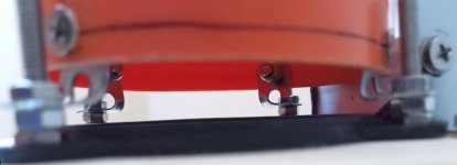
The movement of the prototypes has damaged some gluings so in the photo you can still see the temporary paper clippings used as reinforcements.
Changing the subsonic backing has improved accuracy in the positioning of played instruments and increased dynamics in percussion transients. The previous version was symmetrical with the three pins corresponding to the letters "o". To reduce the possible resonances of the base I moved the feet in correspondence with the letters "x", in particular the rear one is under the L-shaped support bracket. I eliminated the symmetry by choosing 3 distance values from the Fibonacci series (..., 13, 21, 34, ...).
The instrumental measures are similar to the previous ones, on the site I have inserted the download link for the REW file (latest version).
Thanks for the attention.
https://www.claudiogandolfi.it/mdd3a89.html#zc350v2
About 6 months ago I tried to listen to the MDD3ZC350 prototype on the veranda, it stayed there. The floor is in ceramic tiles (in the other room it was in floating parquet), the ceiling is in wood with exposed beams (it was in plasterboard) the walls are: one in masonry, one with windows and two glass windows (there were three in masonry and one in plasterboard). The room is wider and lower 5 x 6 x 2.5 m (was 4 x 4 x 3 m). The combination of the geometry of the room, the materials and the furnishings has significantly improved the quality of the reproduction. I had confirmation of the importance of listening room acoustics. The MDD prototypes perform well in reflective environments and here I have two and a half walls of glass. I also hypothesize that concrete floor and wooden ceiling reduce spurious interactions with sound waves compared to drywall and floating parquet, they absorb less acoustic energy.
Taking advantage of the window, I also tried to power the system with a photovoltaic cell combined with a car battery and a small inverter. The sound hasn't changed but I was able to measure the power absorbed by my system: only 15 watts (PC excluded).
The movement of the prototypes has damaged some gluings so in the photo you can still see the temporary paper clippings used as reinforcements.
Changing the subsonic backing has improved accuracy in the positioning of played instruments and increased dynamics in percussion transients. The previous version was symmetrical with the three pins corresponding to the letters "o". To reduce the possible resonances of the base I moved the feet in correspondence with the letters "x", in particular the rear one is under the L-shaped support bracket. I eliminated the symmetry by choosing 3 distance values from the Fibonacci series (..., 13, 21, 34, ...).
The instrumental measures are similar to the previous ones, on the site I have inserted the download link for the REW file (latest version).
Thanks for the attention.
https://www.claudiogandolfi.it/mdd3a89.html#zc350v2
Attachments
I have no MDD prototype car planned.
A couple of indications for those who want to try.
With a 3” driver the rear acoustic load can be reduced to a volume of about 10 – 20 liters using bent tubes as in the prototype https://www.claudiogandolfi.it/22c71l8.html. The total volume increases in proportion to the surface area of the cone. It can be placed inside the trunk. The TLs have resonant frequencies depending on their lengths, a polymorphic sub can be created that can be tuned with the resonances of the passenger compartment. It would be a mechanical DSP. https://www.diyaudio.com/community/...esonances-for-sub-woofer.370371/#post-6599420.
The frontal acoustic loads I've tested so far are all mounted vertically and require spaces larger than the cockpit of a car. I would give up the MDD effect, I would use diffraction to create acoustic lenses https://www.diyaudio.com/community/...ional-single-drive.342677/page-7#post-6229716. The space between the windshield and the dashboard can be used as a wave guide to create a large horn shared by the two channels (each car model would have different characteristics). Diffraction-generating waveguides can be exploited to correct the frequency response.
MDD vs point source.
I have updated the home page of the site claudiogandolfi.it/, now it is more readable .
I added an analogy that I report here too. I draw a parallel between the graphic images on the covers of two albums, speakers with a point source and MDD loudspeakers.
The first image is from the cover of the album "100% YES" by Melt Yourself Down. Represents a point source audio reproduction system in a listening environment that generates a reflection. In this case the listener has to process two distinct pieces of information, the impression is one of annoyance, listening fatigue.
The second image is from James Blunt's "All the Lost Souls" album cover. Represents an MDD loudspeaker. The multiple and omnidirectional emissions generate many reflections and prevent them from being interpreted as a distinct piece of information. Individual emissions and reflections may differ from the image as a whole. In this case, the listener perceives only one piece of information with background noise.
For the brain, eliminating background noise from one piece of information is easier than managing two pieces of information. A high quality audio system in a treated room will reproduce a very detailed image without listening fatigue. In a room with acoustic problems, an MDD system will give less listening fatigue even if made with lower quality equipment. In rooms treated with quality equipment, even MDD technology can reproduce detailed images without listening fatigue.
https://www.claudiogandolfi.it/
Attachments


Hi jaq775
in the table you have attached the semitones are missing, to have a linear frequency response you must use 12 frequencies. You can avoid always using a number of waveguides equal to the number of notes using the formulas I have already published in the post https://www.diyaudio.com/community/threads/34c9-a-mdd-full-range-speakers.341739/page-4#post-5991238.
In an Excel-like style, N is the number of waveguides, i = 0, ..., N-1, i = N is not used as it is already in the following octave.
For an octave (Lmax = 2 * Lmin)
L = Lmax / POWER (2; i / N)
For two octaves (Lmax = 4 * Lmin)
L = Lmax / POWER (2; i / N * 2)
For three octaves (Lmax = 8 * Lmin)
L = Lmax / POWER (2; i / N * 3)
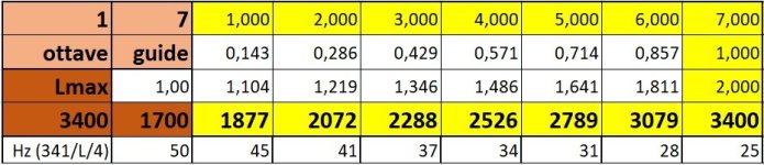
In the front loading (MDDFL) of the prototype MDD3ZC350 V2 the following are used: 3 octaves, 5 waveguides, Lmax = 8Lmin = 2000 mm (379, 574, 871, 1320, 2000mm). The front loading makes the emission omnidirectional even at high frequencies.
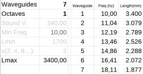
In the rear loading (MDDBL) of the prototype MDD3ZC350 V2 the following are used: 1 octave, 7 waveguides, Lmax = 2Lmin = 3400 mm (1877, 2072, 2288, 2526, 2789, 3079, 3400mm). The rear loading has seven evenly distributed resonant frequencies, the cabinet is neutral at low frequencies.
in the table you have attached the semitones are missing, to have a linear frequency response you must use 12 frequencies. You can avoid always using a number of waveguides equal to the number of notes using the formulas I have already published in the post https://www.diyaudio.com/community/threads/34c9-a-mdd-full-range-speakers.341739/page-4#post-5991238.
In an Excel-like style, N is the number of waveguides, i = 0, ..., N-1, i = N is not used as it is already in the following octave.
For an octave (Lmax = 2 * Lmin)
L = Lmax / POWER (2; i / N)
For two octaves (Lmax = 4 * Lmin)
L = Lmax / POWER (2; i / N * 2)
For three octaves (Lmax = 8 * Lmin)
L = Lmax / POWER (2; i / N * 3)
In the front loading (MDDFL) of the prototype MDD3ZC350 V2 the following are used: 3 octaves, 5 waveguides, Lmax = 8Lmin = 2000 mm (379, 574, 871, 1320, 2000mm). The front loading makes the emission omnidirectional even at high frequencies.
In the rear loading (MDDBL) of the prototype MDD3ZC350 V2 the following are used: 1 octave, 7 waveguides, Lmax = 2Lmin = 3400 mm (1877, 2072, 2288, 2526, 2789, 3079, 3400mm). The rear loading has seven evenly distributed resonant frequencies, the cabinet is neutral at low frequencies.
Claudio, thanks for replying. I think I understand. I made 3 tables based on your answer. In the first one I made your proposal of 7 waveguides, 1 octave. In the second, I expanded it to 2 octaves. And in the third, I changed the most low frequency to make sure that's the way.
Another question is what the maximum diameter can be used. For example, with a 30cm loudspeaker could I use 7 waveguides with 10cm diameter? Is it possible to use a smaller number of even larger diameter waveguides with larger speakers?
Another question is what the maximum diameter can be used. For example, with a 30cm loudspeaker could I use 7 waveguides with 10cm diameter? Is it possible to use a smaller number of even larger diameter waveguides with larger speakers?
Attachments
Hi jaq775
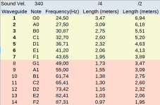
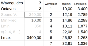
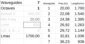
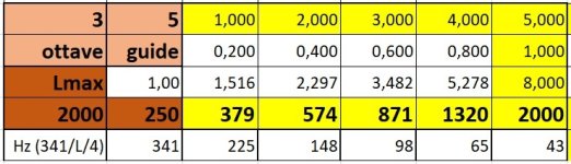
in the last tables it seems that the frequency is not calculated according to the length of the waveguide. I use the formula f = 341 / L / 4 where the length L is entered in meters. I attach two more detailed tables for the acoustic loads of the MDD3ZC350 V2 prototype.
In my posts I take for granted the use of parameters that are not even considered in standard speakers. I will do a mini-tutorial for the design of an MDD system, pending I will answer your questions directly for a 30 cm driver.
MDDFL frontal acoustic load can be the same as prototype MDD3ZC350 V2. The full-range driver emits high frequencies only in the central area, sometimes mounting a second cone with a diameter of a few cm. The shape of the section does not matter, it is advisable not to exceed two cm on the side to prevent lobes from forming at the highest frequencies.
The rear acoustic load MDDBL must have a total section similar to the driver cone surface. 7 guides with 10cm diameter should be fine. The construction will be more difficult than my prototypes due to the increase in power, weight and size, the probability of triggering unwanted vibrations increases exponentially. If you want to reduce the number of guides to 4, 5 or 6, it may be necessary to insert a plug of absorbent material at the end of each guide to enlarge and overlap the resonance bells in the frequency domain. I experimented with foam rubber in the 34c9 prototype.
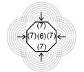
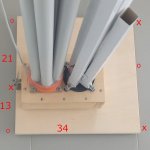
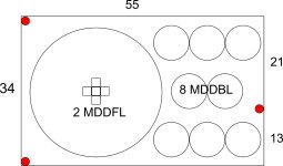
My subsonic resonance stand needs to be rethought from scratch. For the compression chamber, I advise you to place it directly on the ground on three feet. As for the dimensions, I feel comfortable choosing from the Fibonacci series (1, 2, 3, 5, 8, 13, 21, 34, 55, 89, 144, 233, ...), you avoid multiples and a series of unwanted resonances automatically. I am attaching a proposal for a compression chamber, the positions of the feet are indicated in red, I managed to insert seven guides with a diameter of 8 cm. The internal volume of the compression chamber I would choose similar to the Vas of the driver, a minimum internal volume is required to activate the resonances at f = 341 / L / 2 (guide open on both sides) and cover with the same waveguides two full octaves. The height of the compression chamber could be 21 cm.
WHAT I WROTE HAS NOT BEEN TESTED. If I had to use 30 cm drivers I would start from these considerations for a first prototype.
in the last tables it seems that the frequency is not calculated according to the length of the waveguide. I use the formula f = 341 / L / 4 where the length L is entered in meters. I attach two more detailed tables for the acoustic loads of the MDD3ZC350 V2 prototype.
In my posts I take for granted the use of parameters that are not even considered in standard speakers. I will do a mini-tutorial for the design of an MDD system, pending I will answer your questions directly for a 30 cm driver.
MDDFL frontal acoustic load can be the same as prototype MDD3ZC350 V2. The full-range driver emits high frequencies only in the central area, sometimes mounting a second cone with a diameter of a few cm. The shape of the section does not matter, it is advisable not to exceed two cm on the side to prevent lobes from forming at the highest frequencies.
The rear acoustic load MDDBL must have a total section similar to the driver cone surface. 7 guides with 10cm diameter should be fine. The construction will be more difficult than my prototypes due to the increase in power, weight and size, the probability of triggering unwanted vibrations increases exponentially. If you want to reduce the number of guides to 4, 5 or 6, it may be necessary to insert a plug of absorbent material at the end of each guide to enlarge and overlap the resonance bells in the frequency domain. I experimented with foam rubber in the 34c9 prototype.
My subsonic resonance stand needs to be rethought from scratch. For the compression chamber, I advise you to place it directly on the ground on three feet. As for the dimensions, I feel comfortable choosing from the Fibonacci series (1, 2, 3, 5, 8, 13, 21, 34, 55, 89, 144, 233, ...), you avoid multiples and a series of unwanted resonances automatically. I am attaching a proposal for a compression chamber, the positions of the feet are indicated in red, I managed to insert seven guides with a diameter of 8 cm. The internal volume of the compression chamber I would choose similar to the Vas of the driver, a minimum internal volume is required to activate the resonances at f = 341 / L / 2 (guide open on both sides) and cover with the same waveguides two full octaves. The height of the compression chamber could be 21 cm.
WHAT I WROTE HAS NOT BEEN TESTED. If I had to use 30 cm drivers I would start from these considerations for a first prototype.
Attachments
- Home
- Loudspeakers
- Planars & Exotics
- MDD Multi Delays Diffraction (Multi TL, omnidirectional, single drive, ...)